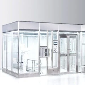
Who owns each wire, pipe, and duct where cleanroom equipment meets the building, and when does that ownership need to be fixed? A cleanroom project can have correct equipment selections and still fail at commissioning if the interface between that equipment and site services was never assigned to a specific source, route, and party. The utility interface is where supplier scope and site scope physically meet, and getting it wrong shows up late, when it is hardest to fix.
Start With Equipment Loads and Available Site Conditions
Every utility interface decision starts from two separate facts that must be compared, not assumed to match. The first is what the equipment actually requires: its declared power, controls and data, water, drainage, compressed air, or exhaust loads, as stated by whoever is supplying that equipment. The second is what the site can actually provide at the point of connection: available capacity, existing routing, and the physical and electrical conditions at that location. These two facts belong to different parties and are established through different processes, and a project only has a workable interface when both have been confirmed and checked against each other.
Where equipment load data is treated as confirmation of site capacity, rather than as one half of a comparison, the project loses the chance to catch a mismatch before it becomes a physical conflict. A declared load tells the reader what the equipment needs under specified conditions; it says nothing about whether the site has that capacity, at that location, in that form. Conversely, a site capacity survey done without the equipment’s actual requirements in hand produces a result that may not match what gets installed. The order matters: equipment loads should be gathered and understood before the available site conditions are treated as sufficient, because the comparison is the actual deliverable, not either input alone.
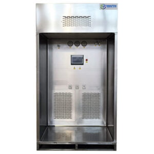
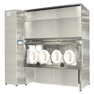
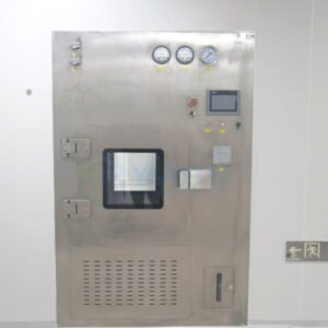
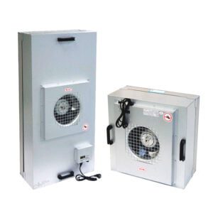
This comparison changes depending on what kind of equipment family is involved. A room-air device drawing continuous power and requiring ducted or plenum access has a different interface profile than a point-of-use item needing only an electrical connection and service access. A local work-zone unit with its own exhaust or recirculation path interacts with the building’s air systems differently than a room-envelope component that has no utility demand at all. Treating all equipment as having the same interface complexity, regardless of family, is where early planning goes wrong, because the comparison step itself needs to be scoped to what that specific equipment actually asks for.
The buyer’s task at this stage is not yet to assign routes or terminations. It is to confirm that someone has stated the equipment’s load and connection requirements in enough detail to compare against the site, and that someone has surveyed the site in enough detail to make that comparison meaningful. Where either side is incomplete, nothing downstream can be reliably fixed.
Map Power, Controls, Water, Air, Drains, and Exhaust by Actual Need
Not every piece of cleanroom equipment needs every utility service, and assuming otherwise creates unnecessary coordination work and potential confusion about what must be checked. The discipline here is to map each service only to the equipment that actually requires it, based on that equipment’s declared needs, rather than applying a standard utility checklist to every item in the project regardless of function.
Power is close to universal across active cleanroom equipment, but controls and data connections are not: some equipment operates on local control with no network or building-management-system interface, while other equipment is designed to report status or accept control signals from a central system. Whether a controls and data connection applies depends on how that specific equipment is configured and how the facility intends to operate it, not on equipment type alone. Water and drains apply where equipment performs a function involving liquid, such as certain washing, humidification, or decontamination-related processes; equipment without that function has no water or drain interface to coordinate, and treating it as if it does wastes design effort and site capacity.
Compressed air applies where equipment uses pneumatic actuation or air-driven function; many cleanroom devices do not use compressed air at all, and this should be confirmed from the equipment’s own data rather than assumed from its general category. Exhaust is similarly conditional: some local work-zone equipment and some BIBO-related systems have a specified exhaust path that must connect to building exhaust infrastructure, while other equipment handles air entirely within a self-contained loop and has no exhaust interface to plan.
The consequence of mapping services by actual need, rather than by category default, is that the project’s utility coordination effort stays proportional to what the equipment actually requires. Where a service is wrongly assumed necessary, the project spends design and installation effort on a connection that will never be used. Where a service is wrongly assumed unnecessary, the project discovers a missing interface at a stage where adding it is far more disruptive. The buyer’s task is to request, for each piece of equipment, an explicit statement of which services apply and which do not, rather than inferring applicability from the equipment’s general description.
Define Source, Route, Termination, and Final Connection for Each Service
| Interface item | Project-specific decision to record | Release boundary |
|---|---|---|
| Service source | Name the agreed source for each service the equipment actually requires. | Keep open until the source is agreed. |
| 경로 | Record the agreed route from the source to the equipment interface. | Freeze before manufacture or site work; late changes may create clashes or rework. |
| Termination point | Record the exact termination point and connection coordinates. | Freeze before manufacture or site work. |
| Final connection | Assign the party responsible for completing the final connection. | Use the proposal and project contract to confirm the actual allocation. |
| Interface test | Record the applicable energization or flow test. | Keep open until the handoff check can be performed. |
| Record ownership | Name who owns the final interface record. | Identify the record owner before release. |
Once a service has been confirmed as applicable to a given piece of equipment, four separate decisions must be made and recorded before that interface can be considered defined: where the service originates, how it gets from that origin to the equipment, exactly where it terminates, and who completes the final connection. Treating these as one undifferentiated “hookup” decision, rather than four distinct points, is where interfaces remain ambiguous even after a project believes it has addressed them.
The source decision identifies the origin point for each service the equipment actually requires, and this must be agreed before anything downstream can be planned, because routing and termination both depend on knowing where a service starts. The route decision records the physical or logical path from that source to the equipment’s connection point; this is a project-specific design decision that depends on the building’s existing infrastructure, the equipment’s location, and any routing constraints the site imposes. The termination point is the precise location and coordinate where the service ends at the equipment interface, and this needs to be exact rather than approximate, because equipment manufacture and site installation both proceed from that fixed point.
The final connection decision is different in kind from the other three: it is not about where the interface is but about who completes it. This is a scope allocation question, answered by the proposal and project contract, not by engineering judgment alone. Where a project assumes the equipment supplier completes final connections by default, without that allocation being confirmed in the governing project documents, there is a risk that the connection falls into a gap between parties, each assuming the other handles it.
A fifth element belongs with this group even though it is not part of the physical interface: the test that confirms the interface actually works once connected, whether that is an energization check for an electrical service or a flow test for a fluid or air service. This test needs an owner and a defined pass condition before the interface can be considered complete, and recording who owns the resulting record prevents the confirmation itself from becoming an unresolved item at a later stage. Interface questions of this kind, including how ducts, power, and controls are confirmed for specific equipment types, extend naturally from this same source-route-termination-connection structure.
Freezing all of these decisions before manufacture or site work begins is what prevents late-stage clashes: once equipment is built to a specific termination coordinate and site work has proceeded on an assumed route, a change to any of the four elements creates rework that a frozen, pre-confirmed interface would have avoided.
Separate Supplier Data from Site Design and Installation Scope
| Scope layer | What belongs here | Allocation boundary |
|---|---|---|
| Supplier data | Declared equipment loads and connection requirements. | This data does not by itself assign site design, routing, or installation scope. |
| Site design | Agreed design for available capacity and connection conditions. | The project allocation must identify the responsible scope. |
| Routing and installation | Agreed routing and installation scope for the site designer and local contractor. | Do not treat supplier data as the site installation allocation. |
| Proposal and project contract | The actual assignment among supplier, site designer, and local contractor. | Treat these project documents as the controlling allocation. |
A recurring source of confusion in cleanroom projects is treating the equipment supplier’s declared data as if it were itself the site design or installation plan. These are different layers of information, produced by different parties, and conflating them leaves gaps that neither party may notice until installation is underway.
Supplier data states what the equipment needs and how it expects to connect: declared loads, connection types, and interface requirements. This data is necessary input to design, but it is not design. It does not specify how a given site routes power to that connection point, where isolation occurs, or who physically installs the final run. Site design is a separate activity, carried out against the site’s actual layout and infrastructure, that takes supplier data as one input among several and produces an agreed routing and connection plan matched to available capacity and site conditions.
Where a project treats supplier data as sufficient on its own, the risk is that no one actually designs the site-side path: the equipment’s requirements are known, but the means of meeting them at this particular site, with this particular building infrastructure, remains undetermined. This gap tends to surface at the point where installation is expected to begin and no one has produced the routing or installation plan that the site design layer was supposed to deliver.
Installation scope is a further layer again: even where design exists, someone has to be assigned to execute it, and this assignment sits with the site designer and local contractor as agreed in the governing project documents. The proposal and project contract are what actually decide this allocation; neither the supplier’s declared data nor the existence of a site design resolves who performs the installation work. A buyer evaluating a cleanroom project, including a modular cleanroom project where multiple equipment families interface with a shared envelope and utility backbone, needs to track these three layers separately: what the equipment needs, how the site is designed to meet that need, and who is contracted to build it. Reviewing supplier-declared equipment information against this three-layer structure is part of what a buyer brings into a quotation or configuration review, because the supplier’s data only answers the first layer, and the project’s own contract documents answer the other two. Clarity on what a cleanroom supplier’s scope actually covers, separate from site design and installation responsibility, is relevant here precisely because the three layers are easy to collapse into one.
Plan Isolation, Service Access, and Functional Interface Checks
| Release item | What must be fixed or checked | 결정 효과 |
|---|---|---|
| Connection coordinates | Freeze the project-specific connection coordinates. | Late changes may create clashes or rework. |
| Isolation points | Freeze each applicable isolation point. | An unresolved point remains an interface open item before release. |
| 서비스 액세스 | Confirm the required access at the interface. | Unresolved access remains an open interface condition before release. |
| Functional interface check | Define the applicable energization or flow test for the connected service. | The handoff is not testable until the relevant check is defined. |
Beyond defining where a service connects, a cleanroom project needs to plan for how that connection will be isolated, accessed, and tested once installed. These three considerations are distinct from the source-route-termination decisions already made, because they concern how the interface behaves during the equipment’s operating life, not just how it is built.
Isolation points determine where a given service can be shut off independently, without disrupting other equipment or other parts of the room. Where equipment needs to be serviced, maintained, or removed without interrupting adjacent systems, an isolation point positioned at or near that equipment’s interface is what makes that possible; where no such point exists, any service action on that equipment forces a wider shutdown than the task actually requires. The condition that determines how many isolation points are needed, and where, is the equipment’s service and maintenance profile: equipment expected to need isolated service has a different isolation requirement than equipment that is rarely touched once commissioned.
Service access concerns the physical space and clearance needed to reach a connection point for inspection, adjustment, or repair. This is a planning decision that has to account for the equipment’s final installed position, including any enclosure, ceiling, or adjacent structure that could obstruct access if not considered in advance. Where access is planned only for the equipment’s footprint and not for its interface points specifically, the result can be a connection that is technically present but difficult to reach once construction is complete.
The functional interface check is what confirms that the physical connection actually delivers what it was designed to. For an electrical connection, this takes the form of an energization check; for a fluid or air connection, a flow test. The specific test that applies depends on which service is involved, and defining that test in advance, rather than deciding on the spot during commissioning, is what makes the handoff from installation to operation a controlled step rather than an improvised one.
All three of these considerations need to be fixed before manufacture or site work proceeds, for the same reason the earlier interface decisions do: a connection coordinate, isolation point, or access requirement that changes after equipment is built or site work is underway creates a mismatch between what was planned and what now needs to be accommodated, and that mismatch becomes rework rather than a simple adjustment.
Record Capacity Confirmation, Witness Points, and Open Items Before Release
| Release record | Evidence to capture | Release treatment |
|---|---|---|
| Capacity confirmation | Confirmation that available site capacity and connection conditions were checked against supplier data. | Record the result before release. |
| Witness point | The agreed energization or flow test point, when applicable. | Record any unagreed witness point as open. |
| 미결 사항 | Any unresolved service, connection, scope, coordinate, isolation, access, test, or record-owner decision. | Record it explicitly before release. |
| Record owner | The person or party assigned to maintain the utility-interface record. | Identify the owner before release. |
The decisions made across equipment loads, service mapping, interface definition, scope allocation, and access planning only hold value if they are captured in a record that the project can check against before release. Release, in this context, means the point at which the project proceeds past the stage where interface decisions can still be adjusted without disruption, so what gets recorded here is effectively the last checkpoint.
Capacity confirmation is the record that the comparison between equipment loads and site conditions was actually performed and resolved, not merely assumed. This is distinct from having gathered both pieces of information; the record needs to show that someone checked one against the other and reached a conclusion, because an unconfirmed comparison is functionally the same as no comparison at all when it comes time to rely on it.
A witness point is the agreed moment, tied to a specific energization or flow test, where someone observes and confirms that an interface performs as expected. Not every interface requires a witness point, but where one has been agreed, it needs to be recorded as such; an energization or flow test that occurs without an agreed witness arrangement produces a result that the project may not be able to treat as a confirmed record later.
Open items are everything that remains unresolved at the point release is being considered: a service whose source has not been agreed, a route not yet confirmed, a termination coordinate not yet fixed, a final-connection allocation not yet settled in the contract documents, an isolation point not yet decided, an access requirement not yet checked, or a test not yet defined. The value of listing these explicitly, rather than treating silence as resolution, is that an unrecorded gap tends to surface only when someone downstream expects a connection that was never actually agreed.
Finally, the record itself needs an owner: someone responsible for maintaining the utility-interface record as the single reference point for what was agreed, confirmed, and left open. Where this ownership is not assigned, the record can exist in fragments across different parties’ files, and reconciling those fragments at a late stage is slower and less reliable than having maintained one record from the start. A project that reaches release with capacity confirmed, witness points agreed, open items explicitly listed, and a named record owner has what it needs to proceed; a project missing any of these elements is releasing on an interface that has not actually been verified, whatever the underlying engineering work may have accomplished.
자주 묻는 질문
Q: Should every cleanroom utility be included in the interface plan?
A: No. Include power, controls and data, water and drains, compressed air, or exhaust only where the equipment actually requires that service. Check each requirement against supplier data, available site capacity, and the proposed connection conditions rather than carrying a generic utility list into the project.
Q: Does the supplier’s equipment data determine who installs each utility connection?
A: No. Declared loads and connection requirements define equipment needs, but they do not assign site design, routing, installation, or the final connection. Use the proposal and project contract to name the responsible party for each part of the interface.
Q: What information should be prepared for a utility interface coordination meeting?
A: Prepare the required services, declared equipment loads, available site conditions, proposed sources and routes, termination points, connection coordinates, isolation points, service access, and applicable interface tests. The meeting should also assign the final connection, each record owner, and every unresolved item.
Q: When should a utility interface remain open instead of being released?
A: Keep it open when site capacity or connection conditions have not been checked against supplier data, or when the route, endpoint, responsibility, isolation, access, test, or record owner is unresolved. Record the specific open item so it is not mistaken for an agreed interface.
Q: How can the project avoid an untestable utility handoff?
A: Define the applicable energization or flow test before release and record any agreed witness point. Also confirm the connection location, isolation, service access, final-connection responsibility, and ownership of the resulting interface record so the check can actually be completed and documented.