Who defines the room’s airflow and pressure intent before equipment gets ordered, and who confirms that the ductwork, power, and controls meeting that equipment actually arrive at the interface points the drawings assume? When these questions stay unanswered until installation, the buyer discovers the gap at the worst possible stage. A cleanroom HVAC interface is not one handoff but several, and each one carries a separate ownership question that a quotation should answer before price comparison begins.
Define the HVAC design basis and each party’s deliverable
| Design-basis item | Definition to put on record | Responsibility boundary |
|---|---|---|
| Room airflow and pressure intent | Intended room airflow and pressure basis | Party that owns the room-level intent |
| Equipment operating points | Operating points the equipment is expected to meet | Party that defines and confirms the operating points |
| Duct interface | Boundary between equipment supply and ductwork | Party responsible for the duct interface |
| Interface de plafond | Boundary between air-delivery equipment or housing and the ceiling system | Party responsible for the ceiling interface |
| Final coordination | Combined design, supply, and interface coordination | Party with final coordination ownership |
The design basis is the set of decisions that everything downstream depends on: what airflow and pressure the room is meant to sustain, and what operating points the equipment is expected to meet to deliver that result. Where this basis is never written down as a shared reference, each party tends to work from its own assumption of what “the design” requires, and these assumptions do not have to be visible as a conflict until the system is tested.
Room airflow and pressure intent belongs to whichever party is accountable for room-level performance, not to whichever party happens to be supplying filtration equipment. An FFU or terminal housing is selected to meet an operating point; it does not generate that operating point independently of the duct static, ceiling grid, and room volume it sits inside. If the equipment supplier is only given a filtration efficiency target and not the pressure and airflow intent behind it, the equipment can be correctly rated and still fail to produce the room condition the project needs. This is why the design basis has to be stated as room-level intent first, with equipment operating points derived from it, rather than the reverse.
Duct and ceiling interfaces are physical boundaries, but they are also decision boundaries. The duct interface determines where equipment supply ends and site ductwork begins; the ceiling interface determines how air-delivery equipment or housing seats into the ceiling system. Where these boundaries are defined late, the equipment arrives sized to a connection that the ceiling trade did not build, or the ceiling opening is cut to a dimension the equipment supplier never confirmed. Neither party is wrong in isolation; the gap exists because no one held final coordination.
Final coordination is a distinct deliverable from design and from supply. It is the function of reconciling the room-level intent, the equipment operating points, and the physical interfaces into one consistent set of drawings and specifications that every other party can build to. A project can have a competent design basis and competent equipment supply and still fail at the interface if no party is assigned to hold that coordination through to issued-for-construction documents. Confirming who performs this role, and at what project stage, determines whether later interface problems are caught on paper or discovered during installation.
Split equipment supply from ducts, power, controls, and field connections
| Scope line | What the quotation should state | Adjacent boundary to allocate |
|---|---|---|
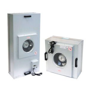
| FFUs and terminal housings | Which FFUs or terminal housings are included in equipment supply | Duct, ceiling, wiring, controls, and field-access interfaces |
| Conduits | Whether ductwork is included or separately allocated | Connection to the supplied FFU or terminal housing |
| Wiring and field connections | Whether wiring and final field connections are included or separately allocated | Connection boundary at the supplied equipment |
| Controls programming | Whether controls programming is included or separately allocated | Handoff from control points, protocol, alarm logic, and interlocks to programming |
| Balancing | Whether field balancing is included or separately allocated | Responsibility for balancing the installed system |
| Field test access | Whether test-access support is included or separately allocated | Responsibility for instrument access during field testing |
Once the design basis is set, the next judgment is where equipment supply stops and adjoining site scope begins. This is not a single line; it runs through several separate interfaces, and treating it as one boundary is how quotations from different suppliers end up describing different amounts of work for the same apparent price.
FFUs and terminal housings are typically the clearest supply item, but “supply” itself needs a boundary. A quotation that lists the units without stating whether duct collars, mounting hardware, or ceiling-grid adaptation are included leaves the buyer to discover the gap when the installer asks what connects to what. Ductwork is a separate scope line entirely: whether it is included with equipment supply or allocated to a mechanical contractor changes who is responsible for the transition piece at the unit’s inlet or outlet, and a quotation silent on this point cannot be compared against one that states it.
Wiring and field connections sit on the same kind of boundary. Equipment can be factory-wired to a terminal block and still require someone to run conduit, land power, and make the final connection on site. Where this connection responsibility is not named, the buyer risks assuming it is included because the equipment is “complete,” when completeness at the factory and completeness at the interface are different claims.
Controls programming is where supply splits from function. A control point can be physically present on a device and still not do anything until it is programmed against the project’s alarm logic and sequence of operation. If the equipment supplier provides the control points but programming is assumed to be done by the controls contractor, the handoff needs to specify what signal, protocol, and documentation the equipment side delivers so the programming side has something to work from.
Balancing and field test access are the two boundaries most often assumed rather than stated. Balancing adjusts the installed system to its intended airflow distribution; it depends on ductwork, dampers, and controls all being in their final configuration, so assigning it to “whoever is on site” rather than to a named party creates ambiguity about when the system is actually ready for performance testing. Field test access, similarly, is a site condition, not an equipment feature, and needs to be confirmed as a deliverable rather than inferred from the equipment’s capability.
Coordinate control points, alarm logic, interlocks, and communication responsibilities
| Controls interface | Project detail to state | Responsibility to assign |
|---|---|---|
| Control points | Control points included in the interface | Party that provides the control points |
| Network protocol | Protocol used for communication | Party that provides and coordinates the protocol interface |
| Alarm logic | Alarm logic included in the project controls | Party that defines and programs the alarm logic |
| Verrouillages | Interlocks included in the project controls | Party that defines and implements the interlocks |
| Capteurs | Sensors included in the controls scope | Party that supplies the sensors |
| Commissioning records | Records to be provided at commissioning | Party that supplies the commissioning records |
Controls interfaces fail less often because of a missing device and more often because no party was assigned to define how the devices communicate with each other and with the building system. Each interface in this group is a decision, not just a component.
Control points must be enumerated as part of the interface, because a control point that exists on the equipment but is not mapped to the project’s control architecture does not produce a usable signal. Where the equipment side and the building-controls side define their point lists independently, mismatches surface only when the systems are connected and the signal that one side expects does not match what the other side sends.
Network protocol is the layer that makes those signals intelligible to each other. If the equipment communicates on one protocol and the building management system expects another, a gateway or translation device becomes necessary, and someone has to be responsible for specifying, procuring, and configuring it. This is a coordination cost that belongs to whichever party is assigned the protocol interface, and leaving it unassigned means it gets resolved reactively, during commissioning, rather than during design.
Alarm logic and interlocks carry a different kind of consequence because they govern how the system responds to an abnormal condition, not just how it reports status. Alarm logic defines what triggers an alert and at what priority; interlocks define what the system does automatically in response to a condition, such as preventing one state until another is confirmed. Where alarm logic is defined by the controls contractor without input from the equipment supplier, the logic may not reflect what the equipment can actually detect or report, and where interlocks are defined without reference to the room’s operational sequence, they can create conflicts between equipment protection and process continuity. Confirming which party defines and programs each of these, and on what basis, is what turns a general control philosophy into a buildable sequence.
Sensors are the physical layer underneath alarm logic and control points; if the sensor scope is not matched to the control-point list, the architecture can be fully designed on paper and still lack the field devices that generate the signals it depends on.
Commissioning records close this interface. They are the evidence that control points, protocol, alarm logic, interlocks, and sensors were verified to function as programmed, and the party responsible for supplying them needs to be named before commissioning starts, not negotiated after it is complete.
Plan balancing, filter installation, test access, and remedial support
| Test-stage item | Project boundary to state | Ce qu'il établit |
|---|---|---|
| Balancing | Party responsible for field balancing | Ownership of balancing before performance testing |
| État d'installation du filtre | Filter installation state when testing occurs | Configuration to which the test results apply |
| Instrument access | Access available for test instruments | Whether the planned test apparatus can reach the required locations |
| Temporary services | Temporary services used for testing and the party that provides them | Test-readiness conditions |
| Remedial work | Party responsible when remedial work is needed | Route from a test finding to corrective work |
| Retesting | Party responsible for retesting after remedial work | Ownership of the repeat test |
| Sign-off | Party with sign-off ownership | Responsibility for closing the test record |
| Conditions d'acceptation | Project-specific performance parameters and acceptance limits; ISO 14644-3 does not set one universal project acceptance limit | Basis used to judge the test results |
Testing readiness is where design and controls decisions either hold up or reveal gaps that were not visible on paper. The sequence from “the system is installed” to “the system is accepted” depends on a series of conditions that need to be fixed in advance, because changing them after testing starts invalidates the result.
Balancing has to happen before performance testing, and the party responsible for it needs to be distinct from the party interpreting the test results, or the same gap in understanding can propagate through both steps. Filter installation state is a related condition: whether terminal filters are installed, and whether they are in their final mounted and sealed configuration, determines what the test results actually represent. A test performed before filters are seated in their final state describes a different system than the one that will operate, and reporting that result as representative of final performance misstates what was measured.
Instrument access is a physical and procedural condition, not an assumption. If the test apparatus required to verify airflow, pressure, or other parameters cannot physically reach the points specified for measurement, the test cannot be performed as planned, and this needs to be confirmed against the room layout before the test date is scheduled, not discovered on the day. Temporary services, where testing requires power, compressed air, or other support not part of the permanent installation, need a named provider, because assuming these will be available on site is a common source of delay when no one has actually committed to supplying them.
Remedial work is where ownership becomes most contested if it is not defined in advance. A test finding that does not meet the acceptance basis requires correction, and the party responsible for performing that correction needs to be established before testing begins, not negotiated after a failed result. Retesting follows the same logic: the party responsible for the repeat test, and the conditions under which it is scheduled, should be fixed alongside the remedial-work assignment, not treated as self-evident.
Sign-off closes the sequence, and it depends on an acceptance basis that is specific to the project. ISO 14644-3 provides test methods, apparatus, and procedures for cleanroom and clean-zone performance parameters, but it does not set one universal project acceptance limit; the actual limits against which results are judged have to be established for the project and agreed before testing, or the test can be completed without anyone being able to say definitively whether it passed.
Close HVAC interface gaps before quotation and contract award
The design basis, the supply-and-scope boundary, the controls architecture, and the test-readiness conditions are not separate problems; they are the same interface described at four different project stages. A gap at one stage tends to surface at the next one, later and harder to resolve, because the parties downstream have already built or programmed around an assumption that was never confirmed.
Closing these gaps before quotation means asking each supplier to state, against the same boundary, what is included and what is not — not simply what equipment is offered. ISO 14644-4 describes the cleanroom project lifecycle, including design, construction, and start-up, without prescribing a particular technology or contractual delivery method, which means the sequence of decisions is a recognized structure but the allocation of responsibility within it remains a project-specific agreement that has to be made explicit rather than inferred from the standard.
Where a project has already defined its room-level airflow and pressure intent clearly, the remaining interface work is narrower: confirming that equipment operating points, duct and ceiling connections, and controls architecture are consistent with that intent, and that test readiness conditions are agreed. Where the room-level intent itself is still undefined, interface coordination cannot meaningfully proceed, because there is no reference point against which to check whether the duct, controls, or test boundaries are correctly drawn. The project team’s first task, in that case, is not comparing quotations but establishing the design basis that the quotations should respond to.
The information a buyer supplies about operating points, interface boundaries, and control responsibilities is also what allows a supplier’s configuration or quotation review to reflect the actual project rather than a generic offering; where FFUs, Boîtiers HEPAou wall and ceiling system components are involved, the duct, power, and ceiling interfaces specific to those product families need to be part of that information, not assumed to be standard across every project. Confirming these boundaries before award does not eliminate every coordination issue that can arise during construction, but it establishes which party is accountable for resolving each one when it does.
Questions fréquemment posées
Q : Is the lowest equipment quotation also the lowest overall HVAC offer?
A : Only if the quotations use the same scope boundary. Compare whether each price includes or excludes ductwork, wiring and field connections, controls programming, balancing, test access, remedial work, and retesting before judging the commercial difference.
Q : Can different parties handle the equipment, ducts, controls, and testing?
A : Yes, provided every handoff is assigned and one party owns final coordination. Record who defines the room airflow and pressure intent, who confirms equipment operating points, and who closes the duct, ceiling, power, controls, and testing interfaces.
Q : What controls information should be settled before requesting a firm quotation?
A : State the required control points, communication protocol, alarm logic, interlocks, sensors, and commissioning records. For each item, assign who defines it, who supplies it, who programs or implements it, and who coordinates the interface.
Q : Does ISO 14644-3 provide one pass-or-fail acceptance limit for every cleanroom project?
A : No. It provides cleanroom and clean-zone test methods, apparatus, and procedures, but the performance parameters and acceptance limits must be set for the specific project and recorded before results are judged.
Q : What should be agreed before field testing if a result does not meet the project acceptance basis?
A : Define who investigates the finding, performs any remedial work, arranges retesting, and owns final sign-off. Also record the filter installation state, balancing responsibility, instrument access, and temporary services so the tested condition is clear.