Understanding Fan Filter Units and Their Critical Role
Clean environments are the backbone of many industries today, from semiconductor manufacturing to pharmaceutical production, biotechnology research to medical device assembly. At the heart of these controlled environments sits a critical component that often goes unnoticed until something goes wrong: the Fan Filter Unit (FFU). These deceptively simple-looking devices are responsible for delivering the ultra-clean, laminar airflow that makes cleanroom operations possible.
I’ve spent over a decade working with cleanroom technologies, and I’ve seen firsthand how the quality of FFU installation directly impacts contamination control outcomes. A properly installed FFU doesn’t just meet specifications on paper—it delivers consistent, reliable performance for years with minimal maintenance issues.
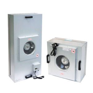
Fan filter units combine a fan system with a high-efficiency particulate air (HEPA) or ultra-low particulate air (ULPA) filter in a single housing unit. They’re designed to pull room air through the fan, push it through the filter media, and deliver a uniform, laminar flow of clean air to the workspace below. This seemingly straightforward function belies the precision engineering that goes into each unit.
YOUTH Tech has developed fan filter units that address many of the common challenges I’ve encountered in the field, particularly their attention to energy efficiency and noise reduction—two factors that typically represent opposing design goals. Their engineering team has clearly prioritized addressing the real-world concerns that facility managers face daily.
Before diving into the installation steps, it’s worth noting that even the most advanced FFU will underperform if improperly installed. A unit misaligned by just a few degrees can create turbulent airflow patterns that compromise contamination control. Inadequate sealing can lead to bypass issues where unfiltered air enters the cleanroom. Improper electrical connections can cause unpredictable performance or premature component failure.
The stakes are high. In semiconductor manufacturing, a single contamination event can destroy products worth millions. In pharmaceutical production, contamination can compromise patient safety. This is why understanding the complete installation process matters so much.
Pre-Installation Planning: Laying the Groundwork for Success
I can’t emphasize enough how critical proper planning is before the first FFU arrives on site. Over the years, I’ve witnessed far too many projects where inadequate planning led to costly modifications, performance issues, and extended timelines.
Begin with a comprehensive site assessment. This includes evaluating the structural integrity of the ceiling system, identifying potential obstructions above the ceiling grid, and confirming access to utilities. The ceiling must be capable of supporting the combined weight of all FFUs—a factor often overlooked until it’s too late. A typical cleanroom might require dozens of units, each weighing between 40-100 pounds depending on the model and size.
Next, calculate the required number of FFUs based on cleanroom classification and application requirements. This involves determining the necessary air change rates, which vary significantly depending on the ISO classification you’re targeting. For example, an ISO Class 6 cleanroom typically requires 50-90 air changes per hour, while an ISO Class 5 environment might need 250-500 air changes hourly.
Here’s a reference table for recommended air change rates by cleanroom classification:
| ISO Classification | Air Changes Per Hour | Typical Applications | FFU Coverage (% of ceiling) |
|---|---|---|---|
| ISO 5 (Class 100) | 250-600 | Aseptic processing, critical semiconductor work | 50-100% |
| ISO 6 (Class 1,000) | 150-250 | Medical device assembly, less critical pharma | 35-50% |
| ISO 7 (Class 10,000) | 60-150 | General electronics, packaging | 25-35% |
| ISO 8 (Class 100,000) | 20-60 | Assembly, general manufacturing | 15-25% |
| ISO 9 | 5-20 | Clean assembly, warehousing | 5-15% |
When determining FFU placement, consider the cleanroom’s workflow pattern. Critical operations requiring the highest air quality should be positioned directly under FFUs or in areas with the highest air change rates. Less critical processes can be located in peripheral zones. This strategic placement approach can optimize both performance and cost.
I once consulted on a project where the client initially wanted uniform FFU placement throughout their cleanroom. After analyzing their processes, we identified that only 30% of the room required ISO 5 conditions, while the remainder could function effectively at ISO 7. By concentrating the FFUs above critical areas, we reduced the total unit count by 40% while still meeting all cleanliness requirements. This not only saved on initial equipment costs but also significantly reduced ongoing energy consumption.
For this planning phase, I highly recommend consulting the detailed fan filter unit specifications to understand the performance capabilities, dimensions, and technical requirements of each model. Different applications may benefit from specific FFU features, such as EC motors for energy efficiency or digital controls for precise pressure management.
Another often-overlooked aspect of pre-installation planning is the coordination with other ceiling-mounted systems. HVAC ducts, sprinkler lines, electrical conduits, and lighting fixtures must all be positioned to avoid conflicts with FFU locations. Creating a comprehensive ceiling plan that accounts for all these elements will prevent costly rework during installation.
Essential Step 1: Proper Handling and Inspection
The moment FFUs arrive on site marks a critical transition in the installation process. How these sophisticated units are handled from delivery through installation can significantly impact their long-term performance and reliability.
When I received a shipment of thirty FFUs for a critical pharmaceutical project last year, I was reminded of the importance of thorough inspection procedures. Despite careful packaging, two units had sustained minor damage during transit—damage that might have gone unnoticed without our detailed inspection protocol. Had these units been installed without repair, they would have compromised the entire cleanroom’s performance.
Begin by inspecting the exterior packaging for any signs of damage or moisture exposure. Document any concerns with photographs before unpacking. Once unpacking begins, follow these specific steps:
- Remove outer packaging carefully, avoiding any sharp tools that might damage the unit
- Check the FFU housing for dents, scratches, or deformation
- Inspect filter media for tears, punctures, or separation from the frame
- Verify that the diffuser screen (if present) is intact and properly attached
- Confirm that all mounting hardware is included and undamaged
- Test the fan motor by hand to ensure it rotates freely without unusual resistance or noise
- Inspect electrical connections for loose wires or damaged components
During a large installation in a semiconductor facility, we discovered that even minor cosmetic damage to the FFU housing could lead to particulate generation once the units were operational. Small paint chips or metal burrs became sources of contamination that were difficult to trace once the clean environment was established.
Document all inspection findings using a standardized checklist that includes the FFU serial number, inspection date, and inspector identification. This documentation serves multiple purposes: it establishes a baseline condition for each unit, provides evidence if warranty claims become necessary, and creates accountability throughout the handling process.
Proper storage of FFUs prior to installation is equally important. Units should be kept in a clean, dry environment with stable temperature and humidity. They should remain in their original packaging until immediately before installation to minimize contamination risk. Never stack FFUs unless explicitly permitted by the manufacturer, as this can damage internal components or distort the housing.
When transporting FFUs within the facility, use dedicated carts with non-marking wheels and adequate support to prevent flexing of the unit. Always carry FFUs in a horizontal position to avoid stressing the internal components. I’ve seen well-meaning installation teams carry FFUs vertically to maneuver through tight spaces, only to discover later that this position had caused the filter media to separate from its frame—a critical failure that wasn’t immediately apparent.
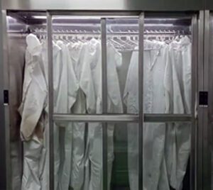
For proper FFU installation in cleanroom environments, always use appropriate personal protective equipment, including gloves, hairnets, and clean coveralls. This protects both the installer and the FFU from contamination. When handling high-efficiency fan filter units for sensitive applications, even fingerprints on critical surfaces can introduce unwanted contamination.
Essential Step 2: Ceiling Grid Preparation and Reinforcement
The integrity of your ceiling grid system directly affects the performance and safety of your FFU installation. Through years of troubleshooting installation problems, I’ve found that ceiling grid issues are among the most common yet preventable causes of FFU performance problems.
Standard suspended ceiling systems are typically designed for lightweight ceiling tiles, not the substantial weight of fan filter units. A 2′ x 4′ FFU can weigh between 40-100 pounds depending on the model. When you multiply this by dozens or even hundreds of units in a large cleanroom, the cumulative load becomes significant.
During a recent installation at a biotech facility, we discovered that the existing ceiling grid was rated for only 2 pounds per square foot—woefully inadequate for supporting FFUs. We had to reinforce the entire system, adding considerable time and expense to the project. This could have been avoided with proper assessment during the planning phase.
First, determine the load rating of your ceiling grid system. For FFU installations, I recommend a minimum of 50 pounds per linear foot capacity for the main runners and cross tees. The suspension system should be rated for intermediate-duty or heavy-duty applications, depending on the FFU weight and density.
When working with specialized cleanroom ceiling grids, refer to this structural capacity comparison:
| Grid System Type | Load Capacity | Recommended FFU Density | Additional Reinforcement Needed |
|---|---|---|---|
| Standard Commercial | 5-10 lbs/ft² | Not recommended | Extensive – not cost-effective |
| Intermediate Duty | 10-15 lbs/ft² | Up to 20% coverage | Yes – for heavier units |
| Heavy Duty | 15-25+ lbs/ft² | Up to 50% coverage | Minimal – at connection points |
| Cleanroom Specific | 25-50+ lbs/ft² | Up to 100% coverage | Rarely – check seismic requirements |
Ceiling grid reinforcement techniques vary depending on your existing infrastructure. Here are the most effective approaches I’ve implemented:
Additional Hanging Points: Increase the number of suspension wires or rods supporting the main runners, especially near FFU locations. The standard 4′ spacing should be reduced to 2′ or less.
Unistrut Reinforcement: Install Unistrut channels above and perpendicular to the main runners. This creates a secondary support structure that transfers the FFU weight directly to the building structure.
Direct Mounting: For critical applications, consider mounting FFUs directly to the building structure using threaded rod systems, bypassing the ceiling grid entirely.
Cross Tee Reinforcement: Install additional cross tees to create a denser grid pattern near FFU locations.
The grid system must also maintain critical alignments for proper airflow patterns. Misalignments as small as 1/8″ can create turbulence that disrupts laminar flow conditions. Use laser alignment tools to ensure grid components are level and square. Pay particular attention to the level of adjacent grid sections where FFUs will be installed.
In seismically active regions, additional considerations apply. Standard seismic clips and bracing may be insufficient for the added weight of FFUs. Consult with a structural engineer to ensure your ceiling system complies with local seismic codes. I’ve worked on installations in California where the seismic bracing requirements doubled the ceiling system cost—an expensive surprise when not factored into initial budgets.
For cleanroom applications, gasket material selection is critical for maintaining room pressurization. The gasket must be compatible with both the FFU housing and the ceiling grid material. Silicone gaskets offer excellent compression recovery and chemical resistance but can be more expensive. Neoprene provides good compression at lower cost but may degrade faster in certain environments.
When selecting appropriate FFU models for your specific application, consider how their dimensions and mounting requirements interact with your ceiling grid system. Some units are designed specifically for T-bar ceilings, while others may require special adapters or custom mounting solutions.
Essential Step 3: FFU Mounting and Securing Techniques
The actual process of lifting and securing FFUs into the ceiling grid requires precision and attention to detail. I’ve supervised hundreds of FFU installations, and I’ve noticed that this step often separates experienced technicians from novices.
Safety comes first. FFUs are bulky, heavy items that must be lifted overhead and maneuvered into tight spaces. Always use at least two people for mounting operations—three is preferable for larger units. Proper lifting equipment makes the job safer and more precise. I prefer using mechanical lift systems specifically designed for ceiling installations rather than relying solely on manual lifting.
I once witnessed an installation where a team tried to save time by having a single person install FFUs. Not only did this create a safety hazard, but the awkward handling resulted in a damaged filter in one unit—a $1,500 mistake that required complete replacement.
Before lifting any units, verify that your installation sequence is logical. I typically recommend installing perimeter units first, then working toward the center of the room. This approach minimizes the risk of damaging already-installed units when positioning subsequent ones.
For the actual mounting process, follow these specific steps:
- Prepare the ceiling opening by cleaning the grid surfaces and applying appropriate gasket material
- Pre-install any mounting hardware to the FFU before lifting
- Raise the FFU carefully to just below its final position
- Align the unit with the ceiling opening, ensuring equal clearance on all sides
- Gently raise the unit into the opening, taking care not to damage the filter media
- Secure the unit according to manufacturer specifications
- Verify the unit is level in all directions
- Seal all gaps between the FFU and ceiling grid
The sealing step deserves special attention. Even small gaps can allow unfiltered air to bypass the FFU, creating “short circuits” that compromise cleanroom performance. Use appropriate cleanroom-compatible sealant for any gaps smaller than 1/8″. For larger gaps, structural modifications may be necessary.
Frequently Asked Questions of FFU Installation
Q: What are the essential tools and equipment needed for FFU installation?
A: For FFU installation, you will need the FFU unit itself, a power supply, ceiling supports, and any additional ducting required. It’s also crucial to have necessary tools like ladders and safety gear. Ensure that the power supply and circuit breakers are turned off before starting the installation.
Q: How do I ensure proper airflow during FFU installation?
A: Proper airflow during FFU installation is crucial. Ensure that the FFU is centered on the ceiling tile to provide even distribution of airflow. Also, verify that the ducts are appropriately sized and there are no leaks to maintain the correct airflow.
Q: What safety precautions should I take during FFU installation?
A: Safety is paramount during FFU installation. Always wear protective gear, and ensure the area is clear of debris. The cleanroom should be closed during installation to prevent contamination. Additionally, handle HEPA filters with care to avoid damage.
Q: How do I connect the power supply for my FFU unit?
A: Connecting the power supply for your FFU unit involves ensuring that all electrical connections are secure. Verify that the voltage matches the field power available. If the FFU is not prewired, a qualified electrician should perform the wiring.
Q: What are the steps to test an FFU after installation?
A: After installing an FFU, turn it on and adjust the airflow to the required CFM. Perform a leak test on the FFU and filter to ensure proper sealing and airflow. Use appropriate measuring devices to verify the airflow settings.
Q: Can FFU units be installed by a single person?
A: While it’s technically possible for one person to install an FFU, it’s highly recommended to have at least two people due to the weight and fragility of the unit, especially when handling HEPA filters. This ensures safety and reduces the risk of damage during installation.
External Resources
- Fan Filter Unit Installation Manual – Provides detailed instructions for installing FFUs, including steps for securing the unit and connecting wiring.
- Installation, Operation & Maintenance Fan Filter Units – Offers a comprehensive guide to installing, operating, and maintaining FFUs, with emphasis on safety and proper sealing techniques.
- Fan Filter Unit Installation Procedure – Describes the installation process for FFUs in cleanrooms, highlighting environmental conditions and safety measures.
- FFDERAJ Fan Filter Unit Installation Instructions – Includes a checklist for installing FFUs, focusing on site preparation, electrical connections, and filter installation.
Related Contents:
- What Are the FFU Requirements for Different Cleanroom Classes?
- FFU vs Laminar Air Flow Unit Comparison
- Installing Ceiling-Mounted HEPA Housing Boxes: 2025 Guide
- FDA/ISO Compliance for Laminar Air Flow Units
- Mastering Clean Room Technology with Fan Filter Units (FFUs)
- USP <797> Compliance for Laminar Units
- ISO 14644-1 Laminar Air Flow Compliance
- Pharma Lab Laminar Air Flow Unit Applications
- Ceiling-Mounted Laminar Air Flow Units Guide


