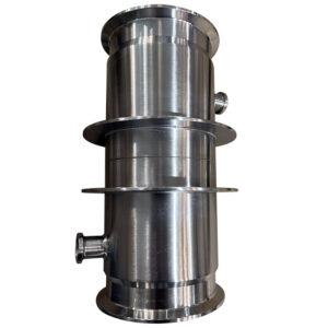
Understanding Laminar Air Flow Units: What They Are and Why They Matter
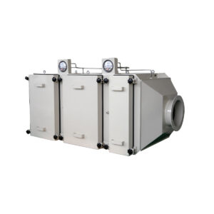
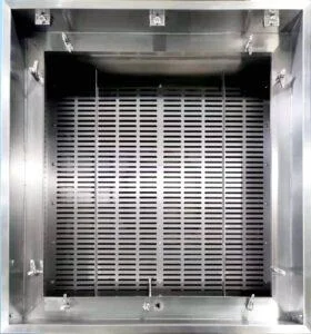
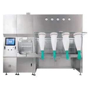
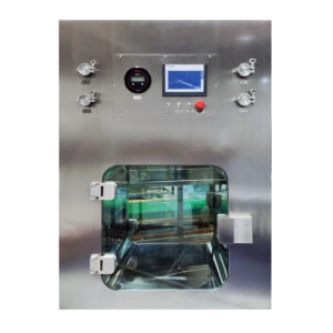
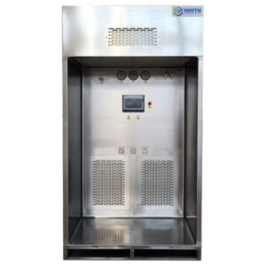
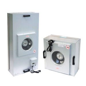
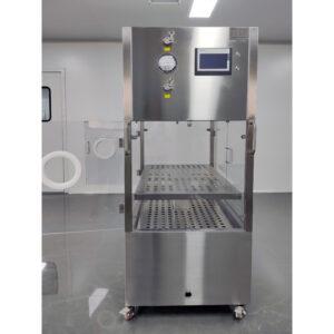
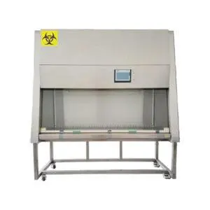
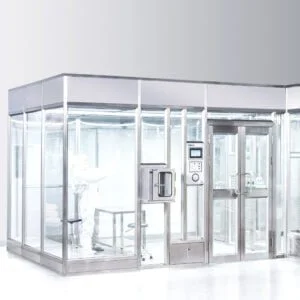
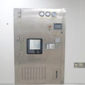
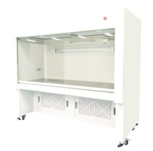
Laminar Air Flow (LAF) units are specialized pieces of equipment designed to create an ultra-clean working environment by providing a unidirectional flow of highly filtered air. Unlike turbulent airflow, laminar flow moves in parallel layers without mixing, effectively sweeping contaminants away from the critical work area. These units serve as the backbone of controlled environments in numerous industries where air cleanliness is paramount.
I’ve spent considerable time working with cleanroom technologies, and the difference between properly and improperly installed LAF systems is stark. A correctly installed unit delivers consistent performance that meets stringent cleanliness standards, while a poorly installed one can compromise product integrity and waste substantial resources.
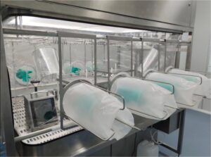
LAF units find essential applications across a spectrum of industries. In pharmaceutical manufacturing, they protect drug products from contamination during formulation and filling processes. In microelectronics, these units shield sensitive components from microscopic particles that could cause device failure. Medical device fabrication, hospitals, laboratory research, and even some specialized food processing operations rely heavily on these systems.
The heart of any LAF unit is its filtration system, typically employing High-Efficiency Particulate Air (HEPA) filters that capture 99.97% of particles 0.3 microns or larger, or Ultra-Low Particulate Air (ULPA) filters with even higher efficiency. This filtration, combined with the laminar flow pattern, creates an environment virtually free of particles, microorganisms, and other contaminants.
YOUTH Tech has established itself as an industry leader by developing LAF systems that combine advanced filtration technology with practical design considerations that facilitate proper installation and maintenance.
Why does proper installation matter so much? Even the highest-quality LAF unit will fail to perform if installed incorrectly. Improper installation can lead to contamination events, inconsistent air quality, wasted energy, premature filter failure, and potentially costly product rejections or recalls. The complexity of LAF unit installation demands careful attention to detail and adherence to established protocols.
Let’s examine the essential steps required to ensure your LAF system performs as intended from day one.
Pre-Installation Preparation: Essential Steps Before Starting
Before unpacking a single component, thorough preparation lays the groundwork for successful installation. This preparatory phase often gets rushed, which I’ve seen lead to complications and delays later in the process.
Site Evaluation and Environmental Assessment
Begin with a comprehensive site evaluation. The installation location must meet specific requirements regarding ceiling height, floor space, and proximity to other equipment. I recently consulted on a project where inadequate ceiling clearance wasn’t identified until the unit arrived, forcing costly modifications to the existing structure.
Room dimensions should allow for the LAF unit plus sufficient surrounding space for maintenance access. Measure doorways, hallways, and elevators to ensure the unit can be transported to its intended location. The structural capacity of the installation area must also be verified, particularly for ceiling-mounted units that may weigh several hundred kilograms.
Environmental factors demand equal attention. Ambient temperature and humidity can affect LAF performance, with most units designed to operate optimally between 18-26°C and 30-60% relative humidity. Excessive vibration from nearby equipment can compromise laminar flow patterns and potentially damage sensitive components.
Technical Specification Review
Obtaining and thoroughly reviewing the manufacturer’s technical documentation is non-negotiable. This documentation provides critical information about:
- Power requirements and electrical specifications
- Ducting and exhaust requirements (if applicable)
- Spatial clearances for operation and maintenance
- Filter specifications and installation requirements
- Control system integration details
During a pharmaceutical facility upgrade, I witnessed installation delays when the team discovered midway that the electrical infrastructure couldn’t support the LAF unit’s power requirements. Thorough advance review would have identified this issue earlier.
Tools and Materials Preparation
Gathering all necessary tools and materials before beginning installation prevents workflow interruptions. Beyond standard tools, you may need specialized equipment such as:
| Tool/Material | Purpose | Special Considerations |
|---|---|---|
| Calibrated anemometer | Measuring air velocity | Must be recently calibrated for accuracy |
| Particle counter | Verifying air cleanliness | Different models for various particle size ranges |
| Level (digital preferred) | Ensuring proper unit orientation | Critical for proper airflow patterns |
| Clean room vacuum | Cleaning during installation | HEPA-filtered to prevent contamination |
| Lint-free wipes | Cleaning surfaces | Must be appropriate grade for cleanroom use |
| Isopropyl alcohol (IPA) | Surface disinfection | Typically 70% concentration |
| Specialized hardware | Unit mounting | Often supplied by manufacturer |
| Silicone sealant | Creating air-tight seals | Must be low-VOC and cleanroom compatible |
Safety Considerations
Safety planning before installation is essential. Personal protective equipment (PPE) requirements should be clearly established, including considerations for both installer safety and cleanroom protocol. Electrical safety measures, including proper lockout/tagout procedures, must be in place before beginning work on power connections.
When installing units in existing cleanrooms, contamination control protocols must be established to minimize disruption to adjacent operations. This might include temporary barriers or scheduling work during facility downtimes.
A project manager I worked with in a medical device facility created a detailed pre-installation checklist that saved countless hours by preventing common oversights. This preparation phase, while sometimes seen as excessive, consistently pays dividends through smoother installation and fewer post-installation issues.
Step-by-Step Installation Guide
The actual installation process requires careful attention to detail and methodical execution. Let’s break down the five essential steps for a successful LAF unit installation.
Step 1: Positioning and Placement
Proper positioning is fundamental to LAF unit performance. The unit must be placed to avoid disrupting the laminar flow pattern with nearby obstructions. During a recent laboratory installation, I found that even a light fixture positioned too close to the LAF unit created turbulence that affected air quality measurements.
For horizontal laminar flow units, maintain a clearance zone of at least 1 meter in front of the unit and ensure no high-traffic pathways cross this zone. For vertical flow units, carefully consider the working height and ensure no overhead obstructions interfere with the airflow.
Leveling the unit is critical and often overlooked. Even slight deviations from level can create uneven airflow patterns. Use adjustable feet or mounting brackets to achieve perfect leveling, and verify with a digital level on multiple points of the unit frame.
For ceiling-mounted units, suspension systems must be installed according to manufacturer specifications and local building codes. These typically require threaded rod supports anchored securely to structural ceiling components, not just to ceiling tiles or grids.
Step 2: Main Component Assembly
Most LAF units from reputable manufacturers come partially disassembled for transport. Assembly should follow the manufacturer’s sequence precisely, as deviations can affect structural integrity and performance.
Begin with the main housing assembly, ensuring all connections are secure but not overtightened, which can deform components. Pay special attention to seals and gaskets, as these prevent air bypass that would compromise filtration efficiency.
The fan system installation requires particular care. Vibration isolation mounts must be properly installed to prevent operational noise and vibration that could affect both the unit’s performance and the work performed within it. Ensure motor orientation is correct and that all electrical connections are properly insulated and secured.
For units with integrated lighting, verify proper installation of fixtures, ensuring they don’t interfere with airflow patterns. Light ballasts should be positioned to minimize heat transfer to the work area and filter media.
Step 3: Filter Installation
HEPA or ULPA filter installation represents the most critical aspect of the entire process. These filters are fragile and extremely sensitive to handling damage. Never touch the filter media directly—always handle filters by their frames only.
Before installation, visually inspect each filter for damage. Even minor perforations or frame deformations can compromise performance. The filter housing should be thoroughly cleaned before filter placement to prevent contamination of the clean side.
When positioning the filter, ensure perfect alignment with the gasket or gel seal channel. For gel seal filters, apply gentle, even pressure until the knife edge is properly embedded in the gel. For gasket seal filters, tighten retaining mechanisms in a diagonal pattern similar to tightening lug nuts on a car wheel to ensure even compression.
Filter integrity testing should be performed immediately after installation, before proceeding to the next steps. This typically involves a DOP (Dispersed Oil Particulate) or PAO (Poly-Alpha Olefin) challenge test to verify the absence of leaks in the filter or its seal.
Step 4: Electrical Connections and Controls
The electrical system is another critical component requiring careful installation. All connections must comply with local electrical codes and manufacturer specifications. Power supply to the unit should match the voltage and phase requirements exactly—even small deviations can damage motor components or control systems.
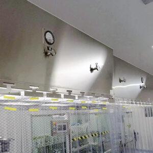
Control panel installation varies by unit design, but should be positioned for easy operator access without interfering with the clean workspace. Control systems often include airflow monitors, filter life indicators, and sometimes more advanced features like pressure differential sensors or remote monitoring capabilities.
For integrated control systems, proper calibration is essential. This typically includes setting baseline values for:
- Airflow velocity readings
- Pressure differential warnings
- Filter life calculations
- UV light timers (if applicable)
- Alarm thresholds
Documentation of all electrical connections and initial control settings should be maintained for future reference and troubleshooting.
Step 5: Final Calibration and Validation
The final step involves comprehensive testing and validation of the installed unit. Start with basic operational verification: power up the unit and confirm all systems function correctly. Check for unusual noise, vibration, or other indicators of improper installation.
Airflow pattern testing confirms that laminar flow is being properly maintained throughout the work zone. This can be visualized using smoke tests (with appropriate test materials) or using thread or ribbon indicators to show directional flow.
Airflow velocity measurement should be performed at multiple points across the face of the filter to ensure uniform velocity, typically targeting 0.45 m/s ±20% for most applications. A calibrated anemometer is essential for accurate measurements.
Particle counting verification confirms the unit achieves the required cleanliness classification. Measurements should be taken at defined points within the work area under operational conditions. Results must meet or exceed the cleanliness standards required for your application (ISO 5/Class 100 for many applications).
Complete the installation by developing thorough documentation of all testing results, initial settings, and baseline performance metrics. This documentation becomes invaluable for future maintenance and recertification.
Common Installation Challenges and Solutions
Even with careful planning, LAF unit installation can present unexpected challenges. Understanding common issues and their solutions can save considerable time and frustration.
Space and Structural Constraints
Finding adequate space for LAF units in existing facilities frequently presents challenges. In a recent biotech laboratory retrofit, we encountered insufficient ceiling height for a standard vertical flow unit. We solved this by selecting a low-profile model that maintained the required air velocity while fitting within the available space.
Structural limitations sometimes prevent hanging ceiling-mounted units in ideal locations. In such cases, floor-standing units can provide an alternative, though they may require more floor space. If ceiling support is insufficient, structural engineers can design reinforcement solutions, though this adds cost and complexity.
For facilities with limited floor space, custom configurations might be necessary. I’ve worked with manufacturers to design corner-mounted units that maximize space utilization while maintaining proper flow patterns. These specialized solutions require more detailed planning but can overcome significant space constraints.
Airflow Obstruction and Pattern Disruption
Physical obstructions near LAF units frequently disrupt laminar flow patterns. HVAC vents, doorways, or even workstation equipment can create turbulence that compromises cleanliness. Visualization testing using smoke or fog can identify these disruptions, allowing for repositioning of either the LAF unit or the obstructions.
Building vibration represents another common challenge, particularly in facilities with heavy equipment nearby. I’ve implemented solutions ranging from enhanced vibration isolation mounts to complete mechanical isolation systems that prevent transmission of vibration to sensitive LAF components.
Electrical and Control System Issues
Facilities often have electrical infrastructure limitations that complicate installation. Insufficient power capacity, incorrect voltage, or unavailable phases can require significant electrical system upgrades. In some cases, I’ve found that coordinating with electrical engineers early in the planning phase to identify these issues saves substantial retrofit costs.
Control system integration presents another challenge, particularly when connecting LAF units to building management systems. Protocol compatibility issues and communication failures can occur. Working with both the LAF unit manufacturer and the facility’s control system integrator is essential to ensure proper data exchange and alarm functionality.
| Challenge | Common Symptoms | Potential Solutions |
|---|---|---|
| Inadequate space | Unit doesn’t fit, or maintenance access is restricted | Low-profile units, custom configurations, repositioning adjacent equipment |
| Structural limitations | Ceiling cannot support unit weight, excessive vibration | Floor-standing alternatives, structural reinforcement, enhanced isolation systems |
| Airflow disruption | Failed smoke tests, inconsistent particle counts | Relocate unit or obstructions, install air barriers, adjust HVAC systems |
| Electrical constraints | Insufficient power, incorrect voltage | Infrastructure upgrades, dedicated power circuits, voltage transformers |
| Control integration | Communication failures, incomplete monitoring | Protocol converters, software updates, custom integration programming |
During a pharmaceutical facility installation project, we discovered that the chosen installation location experienced significant air pressure fluctuations due to nearby automated doors. Rather than relocating the unit, we implemented pressure stabilization controls that adjusted fan speed to compensate for these fluctuations, maintaining consistent laminar flow despite changing room conditions.
Post-Installation Testing and Validation
Thorough validation ensures that your newly installed LAF unit performs to specification and meets regulatory requirements. This critical phase verifies that the installation was successful and establishes baseline performance metrics for future comparison.
Comprehensive Performance Testing
Validation begins with a full functional verification of all systems and components. This includes checking electrical systems, control interfaces, alarm functions, and mechanical components under operational conditions. Documenting these verification steps creates a record of proper initial function.
Air velocity testing measures flow rates across multiple points in the work area. Using a calibrated anemometer, measurements should be taken in a grid pattern across the filter face and work space. For most applications, target velocity is 0.45 m/s (90 fpm) ±20%, though specific applications may have different requirements. I’ve found that measuring at least 9 points for smaller units and up to 25 points for larger units provides sufficient data to identify potential flow irregularities.
Filter integrity testing verifies that HEPA/ULPA filters and their sealing systems are functioning correctly. This typically involves challenging the filter with an aerosol (often PAO or DOP) upstream and measuring for any penetration downstream. Any detectable penetration above allowable limits indicates a leak requiring immediate attention.
Particle counting validation confirms the unit achieves its intended cleanliness classification. Using a calibrated particle counter, measurements should be taken at working height in multiple locations within the protected zone. Results must meet or exceed the required ISO classification for your application—typically ISO 5 (Class 100) for most LAF applications, though some may require ISO 4 or better.
Airflow Visualization Techniques
Smoke studies provide visual confirmation of proper laminar flow patterns. Using a suitable smoke or aerosol generator, introduce a small amount of visible test material at the filter face and observe its flow pattern through the work area. The smoke should move in parallel streams without turbulence or eddy currents, which would indicate installation or design issues.
Dr. Melissa Chang, a cleanroom validation specialist I consulted on a recent project, emphasizes that “visualization testing often reveals subtle airflow disruptions that quantitative measurements might miss. I’ve seen installations that met numerical specifications but failed visual tests due to workstation equipment creating turbulence in critical areas.”
For more sophisticated analysis, some facilities employ computational fluid dynamics (CFD) modeling to analyze airflow patterns and identify potential problem areas before they affect production. While not strictly necessary for validation, this approach can be valuable for complex installations or highly sensitive applications.
Documentation Requirements
Complete documentation is essential for both regulatory compliance and operational reference. A typical validation package should include:
- Detailed installation verification checklist
- Equipment identification and serial numbers
- Filter certification documentation
- Raw data from all performance tests
- Calculated results and comparison to acceptance criteria
- Calibration certificates for all test equipment
- Identified deviations and their resolution
- Photographic documentation of key installation components
- Sign-off by qualified installation and validation personnel
For regulated industries, this documentation becomes part of the facility’s compliance records and will be reviewed during inspections or audits.
Certification Process
Final certification by qualified personnel provides formal verification that the LAF unit installation meets all applicable standards. This certification should be performed by individuals with specific training and experience in cleanroom certification, usually following standards such as ISO 14644 or IEST guidelines.
The certification process typically includes review of all testing data, on-site verification of key parameters, and issuance of a formal certificate documenting compliant performance. This certification establishes the baseline for future recertification, which should occur at regular intervals (typically 6-12 months, depending on application and regulatory requirements).
Maintenance Best Practices After Installation
A well-executed installation is merely the beginning of your LAF unit’s lifecycle. Implementing proper maintenance practices ensures continued performance and extends operational life.
Establishing Monitoring and Maintenance Schedules
Develop a comprehensive monitoring program with clearly defined responsibilities and schedules. Daily visual inspections should check for obvious issues like unusual noise, vibration, or visible contamination. Weekly checks might include differential pressure readings and basic airflow verification. Monthly maintenance typically involves more detailed inspection of components and cleaning of exterior surfaces.
More comprehensive quarterly or semi-annual maintenance should include internal cleaning, thorough inspection of fan systems, and verification of control system accuracy. Annual recertification by qualified technicians verifies ongoing compliance with performance standards.
I’ve implemented a color-coded maintenance calendar system for multiple cleanroom facilities that has dramatically improved compliance with maintenance schedules. By assigning different frequencies to different colors and posting this visibly, maintenance tasks rarely get overlooked.
Filter Management and Replacement
Filter life management requires careful monitoring of differential pressure across the filters. As filters load with particles, this pressure increases, eventually requiring replacement. Most modern LAF units include pressure monitoring systems, but manual verification provides an important backup.
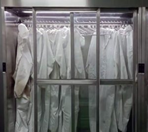
When filters require replacement, follow a documented change protocol that minimizes contamination risk. The area should be properly prepared, with appropriate cleaning before and after the procedure. Personnel should wear suitable cleanroom garments and follow aseptic techniques.
The YOUTH Tech LAF systems with tool-free filter access significantly simplify this maintenance process, reducing both downtime and the risk of damage during filter changes. I’ve found these systems particularly valuable in facilities with frequent filter change requirements.
After filter replacement, integrity testing must be performed to confirm proper installation and performance. This follows the same procedure used during initial validation, challenging the filter with an aerosol and measuring downstream penetration.
Cleaning Protocols
Develop and document specific cleaning protocols for different LAF unit components. Work surfaces should be cleaned before and after each use with appropriate cleanroom-grade disinfectants. External surfaces require regular cleaning to prevent dust accumulation that could be drawn into the airstream.
Interior cleaning requires more careful consideration. Some components can be cleaned with isopropyl alcohol or hydrogen peroxide solutions, while others may require specific cleaners recommended by the manufacturer. Always use low-particle cleaning materials appropriate for cleanroom use.
James Wilson, a cleanroom maintenance specialist with whom I’ve collaborated on several projects, notes that “the single most common maintenance mistake is using inappropriate cleaning materials that leave residues or particles. Even high-quality paper towels can release fibers that compromise cleanroom environments.”
Performance Verification
Regular performance verification confirms continued proper function. This should include:
| Test | Frequency | Acceptance Criteria | Special Considerations |
|---|---|---|---|
| Airflow velocity | Monthly | 0.45 m/s ±20% (or as specified) | Use calibrated equipment, check multiple points |
| HEPA filter integrity | Annually or after filter change | No detectable leakage above spec | Requires specialized equipment and training |
| Particle counting | Quarterly | Meets or exceeds ISO classification | Measurements at working height, multiple locations |
| Smoke pattern test | Semi-annually | Uniform, non-turbulent flow | Visual assessment, may require video documentation |
| Sound level | Annually | Typically < 65 dBA | Excessive noise can indicate mechanical problems |
| Control system accuracy | Quarterly | Within manufacturer’s specification | Compare displayed values to measured values |
Document all verification activities, noting trends that might indicate developing issues. Proactive identification of performance drift allows for planned maintenance rather than emergency repairs.
Case Study: Real-World Installation Example
Last year, I led a project installing three horizontal laminar flow units in a medical device manufacturing facility that provides an instructive example of both challenges and solutions in the installation process.
Project Background
The facility needed to upgrade its existing cleanroom capabilities to meet more stringent ISO 5 requirements for a new product line of implantable medical devices. Space was limited, and production schedules allowed only a narrow window for installation and validation.
The selected units were 99.99% efficient HEPA filter systems with integrated particle monitoring and digital controls. Each unit needed to create a Grade A (ISO 5) environment within an existing Grade C (ISO 7) cleanroom.
Installation Challenges
Our first challenge emerged during site preparation when we discovered that the planned locations had unexpected utility lines running through the ceiling plenum. This required repositioning two units and modifying mounting systems for the third.
Electrical capacity presented another obstacle. The facility’s existing power distribution couldn’t support three additional units without upgrades. Rather than extensive electrical modifications, we worked with the manufacturer to implement a power management system that staggered the startup sequence of the units, preventing simultaneous peak loads.
The most significant challenge involved airflow patterns. Initial smoke testing revealed turbulence caused by the proximity of an HVAC return vent. The turbulence disrupted the laminar flow at one corner of the work area, creating a potential contamination risk.
Innovative Solutions
For the ceiling mounting challenge, we designed a custom suspended framework that distributed the load across a wider area while avoiding utility lines. This added approximately three days to the installation timeline but eliminated the need for costly utility relocation.
The power management solution not only resolved the immediate electrical capacity issue but added an unexpected benefit: the staggered startup reduced the impact of pressure fluctuations in the cleanroom, improving overall stability of the environment.
To address the airflow turbulence, we installed adjustable air diverters on the HVAC return that redirected the room air flow away from the critical LAF work zone. Follow-up smoke testing demonstrated that this simple, low-cost solution completely resolved the turbulence issue.
Performance Results
Post-installation testing exceeded expectations. All three units achieved ISO 4 conditions (better than the required ISO 5) and maintained extremely stable particle counts even during active work processes. The integrated monitoring systems provided robust data for compliance documentation, satisfying regulator expectations during a subsequent inspection.
The facility quality manager later reported that the new installation had decreased product defect rates by approximately 23% compared to the previous setup, directly improving the operation’s bottom line. The project demonstrated that thoughtful installation planning and creative problem-solving can overcome significant challenges without compromising performance or compliance.
Concluding Thoughts on LAF Unit Installation
The process of installing laminar air flow units demands a methodical approach that balances technical precision with practical adaptability. Through years of experience with these systems, I’ve found that successful installations share common characteristics: thorough preparation, careful execution, comprehensive validation, and ongoing maintenance commitment.
The five essential steps outlined—proper positioning, component assembly, filter installation, electrical connection, and final validation—provide a framework for success, but each installation presents unique challenges that require thoughtful adaptation. What works perfectly in one facility may require significant modification in another.
Energy efficiency considerations have become increasingly important in LAF unit installation. Modern units offer variable speed drives and intelligent controls that can reduce energy consumption by 30-40% compared to older models, but these benefits are only realized when the units are properly installed and calibrated. The initial investment in careful installation pays ongoing dividends through reduced operating costs.
Finding the right balance between regulatory compliance and operational practicality remains one of the greatest challenges in this field. While perfect laminar flow conditions might be theoretically ideal, practical installations must accommodate real-world constraints like existing infrastructure, budget limitations, and operational needs.
For those undertaking LAF unit installation for the first time, I strongly recommend consulting with experienced professionals during the planning phase. Their practical knowledge can identify potential issues before they become costly problems. Similarly, manufacturer support can be invaluable, as they typically have extensive experience with a wide range of installation scenarios.
The technology behind laminar air flow continues to evolve, with advances in filter media, control systems, and energy efficiency. However, the fundamental principles of proper installation remain consistent. Attention to detail, rigorous testing, and comprehensive documentation form the foundation of every successful installation.
By following the guidance outlined here, you’ll be well positioned to achieve a successful LAF unit installation that delivers reliable performance, regulatory compliance, and operational efficiency for years to come.
Frequently Asked Questions of LAF Unit Installation
Q: What are the key steps in LAF Unit Installation?
A: LAF Unit Installation involves several critical steps. First, prepare the installation site by cleaning and assessing structural integrity. Next, assemble the main components including housing, fan, and filters. Ensure proper connections and sealing to maintain airflow efficiency. Install and connect the filtration system, ensuring filters are securely seated. Finally, test the unit to confirm optimal performance.
Q: How do I prepare the installation site for LAF Unit Installation?
A: Preparing the installation site for LAF Unit Installation involves thoroughly cleaning the area to remove dust and contaminants. Assess the room layout to choose the optimal location for the unit, considering power supply and workflow. Evaluate the structural integrity of the site and reinforce it if necessary to support the unit’s weight and vibrations.
Q: What is the importance of proper filtration system installation in LAF Unit Installation?
A: Proper installation of the filtration system in LAF Unit Installation is crucial for maintaining a clean environment. Pre-filters and HEPA filters must be installed in sequence, with airtight connections to prevent leakage. Inspect filters for damage before installation and align them correctly to ensure efficient airflow and optimal air purification.
Q: How often should filters be replaced during LAF Unit Installation and maintenance?
A: Filter replacement is essential for maintaining the effectiveness of your LAF unit. Pre-filters should be replaced every 3-6 months, while HEPA filters need replacement every 1-2 years. Regular filter maintenance ensures the unit continues to provide a clean air environment.
Q: What considerations should I make for space and clearance during LAF Unit Installation?
A: When installing a LAF unit, ensure there is sufficient clearance around the unit for airflow and maintenance. Most units require at least 6 inches of clearance on all sides. Adequate ceiling height is also essential, especially for vertical units. Consider the layout of your lab and future expansions to ensure optimal operation and ease of maintenance.
Q: How does the workspace area affect the selection of a LAF unit for installation?
A: The workspace area
External Resources
- How to Install a Laminar Air Flow Unit – Provides a comprehensive guide to installing a laminar air flow unit, including site preparation and component assembly.
- Laminar Airflow Workstation Installation Guide – Offers a step-by-step guide to assembling and installing laminar airflow workstations, emphasizing safety and operational efficiency.
- Laminar Flow Hood Assembly – Includes detailed instructions and a video guide for assembling both vertical and horizontal laminar flow hoods.
- SOP for Laminar Air Flow Unit – Establishes a standard operating procedure for the operation of laminar air flow units, focusing on maintenance and cleaning protocols.
- Cleanroom Laminar Flow Unit Installation – Although not directly titled “LAF Unit Installation,” this resource offers insights into installing laminar flow units within cleanroom settings.
- Commissioning and Installation of LAF Units – Provides guidance on commissioning and installing laminar air flow units, ensuring compliance with regulatory standards.
Related Contents:
- Pharma Lab Laminar Air Flow Unit Applications
- Laminar Air Flow Units for Contamination Control
- USP <797> Compliance for Laminar Units
- The Ultimate Guide to LAF Units: Everything You Need to Know
- Fan Filter Units or Laminar Flow Hoods: Which to Choose?
- Portable vs Fixed Laminar Air Flow Units
- Horizontal vs Vertical Laminar Units 2025
- Industrial vs Lab Laminar Air Flow Units
- Microbiology Lab Laminar Air Flow Unit Uses


