Understanding FFU Airflow Fundamentals
The first time I stepped into a semiconductor fabrication facility, I was struck not by the advanced technology or the complexity of the machines, but by the invisible element that made it all possible: the carefully controlled air. The facility manager explained how critical properly designed FFU airflow patterns were to their entire operation, and that conversation fundamentally changed my understanding of cleanroom environments.
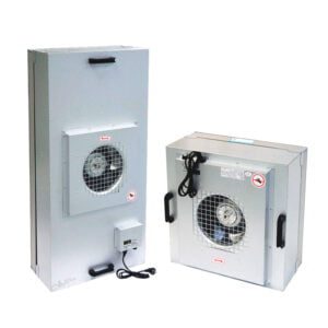
Fan Filter Units (FFUs) represent the backbone of controlled environments where contamination control is paramount. These seemingly simple devices combine motorized fans with high-efficiency filtration to deliver unidirectional, clean airflow—creating the foundation for contamination-free manufacturing and research. But beneath this apparent simplicity lies a complex interplay of fluid dynamics, mechanical engineering, and precision control.
At its core, an FFU works by drawing room air through a fan and forcing it through a HEPA or ULPA filter. This creates laminar airflow—a pattern where air moves in parallel layers with minimal mixing. When properly designed, this smooth, unidirectional flow sweeps particulates away from critical processes. YOUTH Tech has pioneered significant advancements in this field, focusing on the precise engineering required for optimal airflow management.
The fundamental principle behind effective FFU operation is the creation of laminar flow. Unlike turbulent flow, where air mixes chaotically, laminar flow moves in orderly, parallel paths. This orderliness isn’t just an engineering preference—it’s essential for consistent particle removal. When air travels in predictable patterns, it effectively “sweeps” contaminants away from critical areas rather than recirculating them.
Several components within an FFU system directly influence airflow characteristics:
- Fan design and motor: The heart of the system that determines flow rate and uniformity
- Filter media: Affects resistance, pressure drop, and flow distribution
- Housing construction: Influences air entry and exit patterns
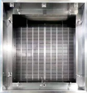
- Diffuser screens: Helps distribute air more evenly across the filter face
The importance of proper FFU airflow patterns extends beyond basic contamination control. In semiconductor manufacturing, even nanometer-scale particles can destroy product yield. In pharmaceutical environments, airborne microorganisms must be prevented from reaching critical products. These requirements have driven the development of increasingly sophisticated airflow management techniques.
What many don’t realize is that the relationship between airflow velocity, pattern uniformity, and particle control isn’t linear. Too little airflow fails to provide adequate protection; too much can create turbulence that actually increases contamination risk. Finding that balance—typically between 0.3 and 0.5 meters per second for most applications—requires both science and experience.
Key Factors Influencing Airflow Patterns in FFUs
The placement of FFUs within a room creates the foundation for effective airflow patterns. I learned this lesson the hard way during a cleanroom redesign project when seemingly minor positioning changes resulted in significant performance variations. Room dimensions, ceiling height, return air pathways, and the relationship between supply and return all fundamentally shape how air moves through the space.
One often overlooked aspect is the interaction between FFUs themselves. When multiple units operate in proximity, their airflow patterns can either reinforce or disrupt each other. This interaction creates what engineers call “flow coupling”—a phenomenon where airstreams from adjacent FFUs affect each other’s performance. Proper spacing and alignment are crucial for minimizing these effects.
The high-efficiency FFU systems with optimized airflow patterns incorporate sophisticated filter media that balances several competing requirements. Filter selection directly impacts airflow in several ways:
- Pressure drop: Higher efficiency filters typically create more resistance, requiring stronger fans
- Particle capture efficiency: Different filter classes (H13, H14, U15, etc.) create different flow characteristics
- Media uniformity: Variations in filter media density create corresponding variations in airflow
Fan design represents another critical element in the airflow equation. Multiple parameters including impeller design, motor type, blade configuration, and rotational speed all influence how air moves through the system. EC (electronically commutated) motors have become increasingly popular due to their precise speed control, which allows for fine-tuning of airflow patterns.
The table below illustrates how different fan configurations affect airflow characteristics in typical FFU systems:
| Fan Configuration | Airflow Uniformity | Energy Efficiency | Noise Level | Typical Applications |
|---|---|---|---|---|
| Backward-curved centrifugal | Excellent (±5-10%) | High | Low | Semiconductor, pharmaceutical |
| Forward-curved centrifugal | Good (±10-15%) | Moderate | Moderate | General cleanroom use |
| Mixed flow | Very good (±7-12%) | High | Very low | Medical device manufacturing |
| EC motor with variable speed | Excellent (±5-8%) | Very high | Adjustable | All critical applications |
Pressure differentials within the cleanroom environment create the driving force for air movement. These differentials don’t just push air through filters—they shape how air circulates throughout the entire space. During a consultation at a medical device facility, I discovered their contamination issues stemmed not from filter problems but from inadequate pressure cascade between adjacent spaces.
Room obstructions present significant challenges to maintaining uniform FFU airflow patterns. Light fixtures, sprinkler heads, gas distribution systems, and structural elements can all disrupt otherwise laminar flow. The key is not necessarily eliminating these obstructions (which is often impossible) but accounting for them in the overall airflow design.
Temperature gradients, though subtle, exert surprising influence over airflow patterns. Warmer air naturally rises while cooler air falls, creating vertical currents that can disrupt laminar flow. This becomes particularly problematic in environments with heat-generating equipment. Effective thermal management strategies must be integrated with airflow planning.
The relationship between supply and return air paths deserves special attention. In many facilities, I’ve observed that return air pathways receive far less design consideration than supply systems, yet they’re equally important for maintaining proper airflow patterns. Poorly positioned returns can create cross-currents that undermine even the best FFU configuration.
Advanced Techniques for Airflow Optimization
Computational Fluid Dynamics (CFD) modeling has revolutionized how we approach FFU airflow pattern optimization. Rather than relying solely on experience and rules of thumb, we can now simulate complex airflow scenarios before installation. During a pharmaceutical cleanroom project, our CFD models revealed potential flow disruptions that would have been difficult to predict using conventional methods.
Dr. Wei Sun, a respected ASHRAE Fellow with decades of cleanroom design experience, emphasizes that “CFD modeling allows us to visualize the invisible—to see airflow patterns, velocity gradients, and potential areas of turbulence before a single component is installed.” This predictive capability has proven invaluable for complex installations where multiple variables interact.
However, CFD modeling does have limitations. The accuracy of simulations depends entirely on the quality of input data and boundary conditions. As one engineer wryly noted during a conference presentation, “garbage in, garbage out.” Effective modeling requires detailed specifications of all system components, accurate room dimensions, and realistic operational parameters.
Beyond simulation, velocity profile mapping provides critical insights into actual FFU performance. This technique involves measuring air velocity at multiple points across the filter face and throughout the room to create a comprehensive map of airflow patterns. The resulting data reveals non-uniformities that might compromise contamination control.
| Measurement Location | Target Velocity Range | Common Problems | Optimization Approaches |
|---|---|---|---|
| Filter face center | 0.45-0.50 m/s | Center high/low pattern | Fan speed adjustment, diffuser modification |
| Filter face perimeter | Within ±20% of center | Edge falloff, corner effects | Housing design improvements, perimeter sealing |
| Work surface (critical zone) | 0.36-0.46 m/s | Velocity decay, lateral drift | Room return optimization, obstruction management |
| Room perimeter | Controlled return flow | Recirculation zones, back-mixing | Strategic return placement, pressure balancing |
One fascinating technique I’ve implemented involves adjustable diffuser screens that can be tuned to compensate for inherent non-uniformities in airflow. By creating variable resistance across the filter face, these screens help equalize velocity profiles without requiring major system modifications. The innovative FFU airflow optimization technology integrates such features to enhance performance.
Energy efficiency concerns have driven significant innovation in airflow optimization. The challenge lies in balancing contamination control requirements against operating costs. After conducting an energy audit for a large semiconductor facility, I was surprised to discover their FFU systems consumed nearly 60% of the facility’s total energy—highlighting the importance of efficiency improvements.
Several strategies have proven effective for optimizing efficiency while maintaining proper airflow patterns:
- Demand-based control systems that adjust FFU operation based on actual cleanliness requirements
- Airflow visualization to identify and eliminate over-ventilated areas
- Strategic zoning of cleanliness levels to avoid over-specification
- Low-pressure-drop filter media that reduces fan energy requirements
The concept of “sufficient uniformity” rather than “perfect uniformity” represents an important paradigm shift in airflow design. While perfect laminar flow might be theoretically ideal, it’s often unnecessary and prohibitively expensive. The key is identifying the minimum acceptable uniformity for specific applications and optimizing to that standard.
Common Airflow Pattern Challenges and Solutions
Turbulence represents perhaps the most fundamental challenge in FFU airflow pattern management. Unlike laminar flow, where air moves in parallel paths, turbulent flow creates swirls, eddies, and unpredictable movements that can transport contaminants into critical areas. I’ve witnessed seemingly minor installation details—poorly sealed ceiling penetrations, improperly tensioned filter gaskets, even light fixture placement—create significant turbulence issues.
Identifying turbulence often requires visualization techniques. During a troubleshooting session at a microelectronics facility, we used neutrally buoyant smoke to reveal disrupted airflow patterns that weren’t apparent from velocity measurements alone. The smoke clearly showed vortices forming near ceiling mounted equipment, creating potential contamination pathways.
Dead zones—areas with minimal air movement—present another common challenge. These stagnant regions can allow particles to accumulate and then periodically release into the environment. They typically form in corners, under workstations, and behind equipment. The most effective solution involves strategic placement of return air pathways to create gentle movement in these areas without disrupting the primary laminar flow.
This table summarizes common airflow pattern problems and their potential solutions:
| Airflow Issue | Potential Causes | Detection Methods | Remediation Approaches |
|---|---|---|---|
| Turbulence | Filter bypass leakage, obstructions, improper installation | Smoke visualization, hot-wire anemometry, particle counting | Seal leaks, relocate obstructions, adjust flow rates |
| Dead zones | Poor return placement, equipment blocking flow, incorrect pressure balancing | Smoke visualization, particle deposition testing | Add local returns, modify equipment placement, adjust pressure differentials |
| Flow non-uniformity | Filter loading differences, fan inconsistencies, duct design | Velocity mapping, pressure differential testing | Filter replacement, fan balancing, system reconfiguration |
| Cross-contamination | Inadequate pressure cascades, door opening effects, improper room balancing | Tracer gas studies, pressure monitoring | Adjust room pressurization, add air locks, modify operational procedures |
Ceiling obstructions represent a particularly challenging problem in many cleanroom environments. HVAC ducts, sprinkler pipes, lighting fixtures, and structural elements can all disrupt otherwise uniform airflow patterns. During a pharmaceutical facility design review, we discovered that proposed ceiling-mounted process piping would create significant disruptions in critical aseptic filling areas.
The solution involved a comprehensive approach:
- Relocating non-essential services outside critical zones
- Streamlining necessary obstructions with aerodynamic shrouds
- Creating computational models to predict disruption patterns
- Adjusting nearby FFU placement and settings to compensate
- Implementing additional monitoring in potentially affected areas
Recovery time after disruptions provides another important metric for evaluating FFU airflow pattern effectiveness. When doors open, people move, or processes change, how quickly does the system restore proper airflow conditions? Testing recovery time during qualification can reveal fundamental design flaws that might otherwise go unnoticed until production issues arise.
The advanced fan filter units with superior recovery characteristics incorporate design features specifically engineered to minimize recovery time after disruptions. These include optimized fan response curves, intelligent control systems, and aerodynamic housing designs that work together to quickly reestablish proper airflow patterns.
Measurement and Verification of FFU Airflow Patterns
Consistent measurement protocols are essential for meaningful evaluation of FFU airflow patterns. ISO 14644-3 provides standardized testing procedures, but practical implementation requires careful attention to detail. During a validation project at a contract manufacturing facility, I discovered their previous testing had used inconsistent measurement heights, creating misleading data that masked significant airflow issues.
The selection of appropriate instrumentation significantly impacts measurement accuracy. Various technologies offer different advantages:
- Hot-wire anemometers: Provide precise point measurements but can be directionally sensitive
- Vane anemometers: Less precise but capture average flow over larger areas
- Ultrasonic anemometers: Measure three-dimensional flow components without disturbing the airstream
- Particle counters: Indirectly assess airflow effectiveness through contamination measurement
Testing should occur under multiple operational conditions. I’ve seen systems that performed perfectly during at-rest testing fail dramatically once production equipment and personnel were introduced. Comprehensive verification includes testing under:
- As-built conditions (empty room)
- At-rest conditions (equipment installed but not operating)
- Operational conditions (normal production activities)
- Worst-case scenarios (maximum personnel, equipment operation)
Airflow visualization techniques provide invaluable qualitative insights that complement quantitative measurements. These techniques include:
| Visualization Method | Application Scenarios | Advantages | Limitations |
|---|---|---|---|
| Neutrally buoyant smoke | Initial FFU commissioning, problem investigation | Directly reveals flow patterns, turbulence identification | Temporary effect, difficult to document |
| Thread tufts | Continuous monitoring, troubleshooting | Simple implementation, persistent indication | Limited sensitivity, only shows surface flow |
| Laser particle imaging | Research applications, detailed analysis | Precise quantification, captures 3D effects | Expensive, requires specialized expertise |
| Fog machine visualization | Large area assessment, training demonstrations | Dramatic visual effect, covers extensive areas | Potential contamination concerns, temporary |
Interpreting measurement data requires understanding normal variation versus significant problems. Not all non-uniformity indicates a system failure. When examining detailed FFU performance data from velocity profile testing, I look for patterns that suggest systemic issues rather than isolated variations.
Key indicators include:
- Consistent directional bias across multiple measurement points
- Progressive degradation of uniformity over time
- Correlation between non-uniformity and environmental factors
- Persistent turbulence in critical process areas
David Kimbrough, an experienced contamination control engineer I’ve collaborated with on several projects, emphasizes the importance of contextual interpretation: “The numbers themselves mean little without understanding the specific process requirements. A velocity variation that’s catastrophic for semiconductor lithography might be completely acceptable for general pharmaceutical manufacturing.”
Documentation practices should capture not just current conditions but also establish baselines for future comparison. Detailed records of initial testing provide invaluable reference points when troubleshooting future issues or evaluating the impact of system modifications.
Case Studies: Successful FFU Airflow Pattern Optimization
A semiconductor manufacturing facility in Arizona presented a particularly challenging case for airflow optimization. Their photolithography area required exceptionally uniform airflow to maintain precise temperature control during critical exposure processes. Despite installing high-quality FFUs, they experienced inconsistent results with periodic yield losses.
Analysis revealed that their FFU airflow patterns were being disrupted by thermal stratification. The heat generated by stepper motors created temperature gradients that induced vertical air currents, disrupting the carefully designed laminar flow. The solution required a comprehensive approach:
- Implementation of specialized FFUs with integrated thermal management
- Modified ceiling return configuration to capture rising warm air
- Strategic placement of temperature sensors for continuous monitoring
- Adjustment of system controls to respond to thermal variations
The results were impressive: yield increased by 7%, and temperature variation across critical processes decreased from ±0.8°C to ±0.3°C. This improvement translated to approximately $2.4 million in annual savings from reduced product losses.
Another instructive case involved a pharmaceutical aseptic filling operation where airflow pattern issues contributed to occasional sterility test failures. Initial investigation focused on HEPA filter integrity, but comprehensive testing showed all filters meeting specifications. The real problem emerged when we analyzed airflow patterns during actual production operations.
Personnel movement, particularly the opening and closing of rapid roll doors between classified areas, created temporary disruptions in FFU airflow patterns. These disruptions persisted longer than expected, allowing potential contaminants to enter critical areas during filling operations.
The implemented solution included several components:
- Upgrading to high-performance FFUs with rapid recovery capability
- Modifying operational procedures to allow recovery time after door operations
- Installing visual indicators showing real-time airflow conditions
- Implementing automated particle monitoring with alarm thresholds
The facility saw immediate improvement, with sterility test failures decreasing by 92% in the six months following implementation. Equally important, they gained a deeper understanding of the dynamic nature of cleanroom airflows rather than viewing them as static systems.
A third case worth examining involved a medical device manufacturer producing implantable products. Their challenge centered on balancing energy efficiency with stringent cleanliness requirements. Initial designs called for 100% ceiling coverage with FFUs—a configuration that would have created excellent airflow patterns but at prohibitive operating costs.
Through careful analysis and modeling, we developed a configuration using approximately 35% ceiling coverage with strategically placed FFUs. Key to success was the implementation of:
- Computational modeling to predict airflow patterns with various configurations
- Targeted placement of FFUs over critical process areas
- Modified return air strategies to maintain proper flow patterns
- Comprehensive monitoring to verify performance
The resulting system maintained required ISO 5 conditions while reducing energy consumption by approximately 55% compared to the original design. This translated to approximately $175,000 in annual energy savings while meeting all regulatory requirements.
These cases highlight an important lesson: successful FFU airflow pattern optimization requires understanding the specific requirements of each application rather than applying generic solutions. The constraints, critical parameters, and acceptable compromises vary significantly between industries and even between different processes within the same facility.
Future Trends in FFU Airflow Technology
The integration of smart monitoring systems represents perhaps the most significant advancement on the horizon for FFU airflow pattern management. Unlike traditional systems that operate at fixed settings regardless of conditions, these intelligent systems continuously adapt to changing environments. During a recent technology conference, I witnessed a demonstration where FFUs automatically adjusted their operation in response to increased particle counts—something that would have required manual intervention just a few years ago.
These smart systems leverage several technological components:
- Distributed sensor networks that monitor air quality, velocity, and pressures
- Machine learning algorithms that identify patterns and predict potential issues
- Adaptive control systems that automatically adjust operating parameters
- Data analytics platforms that provide insights for continuous improvement
Energy efficiency will continue driving innovation in FFU airflow pattern optimization. Recent research from the Lawrence Berkeley National Laboratory suggests potential energy savings of 35-50% through advanced control strategies without compromising cleanroom performance. These approaches focus on demand-based operation rather than continuous full-capacity running.
One particularly promising development involves miniaturized anemometer arrays integrated directly into FFU systems. These arrays provide continuous, real-time feedback on airflow patterns, allowing for immediate adjustments when non-uniformities develop. Early implementations show significant improvements in both consistency and energy efficiency.
Emerging research in computational modeling points toward increasingly sophisticated simulation capabilities. During a recent industrial-academic collaboration project, I worked with researchers developing models that can predict airflow disruptions from personnel movement—something previously considered too complex for practical simulation. These advanced models promise to revolutionize both design and operational aspects of cleanroom management.
The application of machine learning to optimize FFU settings represents another frontier. By analyzing thousands of operational parameters and correlating them with contamination events, these systems can identify non-obvious relationships that human operators might miss. One pharmaceutical company implementing this approach reported a 23% reduction in contamination events after deployment.
Interest in sustainable cleanroom design continues growing, with FFU airflow optimization playing a central role. New approaches include:
- Hydronic cooling integrated with FFUs to reduce thermal impact on airflow patterns
- Recovery systems that capture and reuse energy from exhaust air
- Variable geometry components that adapt to changing operational needs
- Biomimetic designs inspired by natural airflow patterns
These innovations aren’t merely theoretical—many are already being implemented in leading facilities. During a recent visit to a newly commissioned semiconductor fab, I observed several of these technologies working together to create exceptionally uniform airflow patterns while consuming significantly less energy than conventional designs.
The future will likely see increasing integration between FFU systems and overall building management. Rather than operating as isolated systems, FFUs will become nodes in comprehensive environmental control networks—responding to changing conditions throughout the facility to maintain optimal performance while minimizing resource consumption.
Conclusion: Balancing Theory and Practice in FFU Airflow Design
Optimizing FFU airflow patterns remains as much art as science. While we’ve developed sophisticated models, measuring techniques, and control systems, successful implementation still requires judgment, experience, and a deep understanding of specific application requirements. The semiconductor engineer focusing on submicron particle control has very different needs than the pharmaceutical manufacturer concerned with viable organisms—yet both rely on properly designed FFU airflow patterns.
Throughout my career working with cleanroom systems, I’ve found that the most successful projects balance theoretical ideals with practical constraints. Perfect laminar flow might be the textbook goal, but real-world installations must accommodate structural elements, process equipment, personnel movement, and economic limitations. The key is identifying what aspects of airflow performance are truly critical for specific applications and optimizing those parameters accordingly.
Several principles have proven consistently valuable:
- Begin with clear, quantifiable requirements based on actual process needs
- Utilize computational modeling to evaluate design options before implementation
- Apply comprehensive measurement protocols to verify performance
- Recognize that initial commissioning is just the beginning—ongoing monitoring and adjustment are essential
Energy considerations and sustainability will continue driving innovation in this field. The days of designing systems with excessive margins “just to be safe” are fading as facility operators recognize both the environmental and financial costs of overdesigned systems. More sophisticated approaches now allow us to maintain critical parameters while significantly reducing resource consumption.
For those implementing or optimizing FFU systems, I recommend maintaining a flexible, inquisitive approach. The field continues evolving rapidly, with new technologies and methodologies emerging regularly. What represented best practice five years ago may now be outdated. Continuous learning, collaboration with colleagues across disciplines, and willingness to question established assumptions all contribute to successful outcomes.
The ultimate measure of success remains the same: consistently providing an environment that supports the intended processes while minimizing resources and maximizing reliability. When properly designed, installed, and maintained, FFU systems create the invisible foundation upon which countless critical industries depend—from the smartphones in our pockets to the medicines that save lives.
Frequently Asked Questions of FFU airflow patterns
Q: What are FFU airflow patterns, and why are they important?
A: FFU airflow patterns refer to the distribution and movement of air from Fan Filter Units, which are crucial in maintaining cleanliness and air quality in controlled environments like cleanrooms. Uniform airflow is essential for preventing turbulence and ensuring that particles are efficiently removed from the air.
Q: How do FFU airflow patterns affect air cleanliness in cleanrooms?
A: FFU airflow patterns significantly impact air cleanliness by influencing how particles are dispersed and removed. Uniform airflow helps prevent turbulence, which can re-suspend particles, while non-uniform airflow can lead to areas of poor air quality.
Q: What factors influence FFU airflow patterns?
A: Factors influencing FFU airflow patterns include supply air face velocity, filter size, and the design of the FFU itself. Higher face velocities can reduce particle concentrations, while larger filters may provide a broader range of clean air distribution.
Q: How can FFU airflow uniformity be achieved?
A: Achieving uniform FFU airflow involves using internal baffling systems, plenum chambers, and perforated exit plates to ensure even air pressure and distribution across the filter face. This setup helps maintain consistent air velocity and flow.
Q: What are the consequences of non-uniform FFU airflow patterns?
A: Non-uniform FFU airflow patterns can lead to turbulence, causing particles to be re-suspended and reducing the overall cleanliness of the environment. This can compromise the effectiveness of cleanrooms and controlled spaces.
Q: How can FFU airflow patterns be optimized for specific environments?
A: Optimizing FFU airflow patterns involves selecting the appropriate FFU size and design based on the specific requirements of the cleanroom or controlled environment. Adjusting supply air velocities and using multiple FFUs can also enhance air distribution and cleanliness.
External Resources
Analysis and Experiments on the Characteristics of Airflow – This study examines the airflow patterns from a fan filter unit (FFU), focusing on the spread of clean air along both axial and lateral directions. It discusses how supply air face velocity affects particle concentration and air cleanliness.
Airflow Uniformity and Fan Filter Units – This resource discusses the importance of airflow uniformity in FFUs, highlighting how design features like internal baffling systems ensure consistent air distribution across the filter face.
Fan Filter Units FFU – This article provides an overview of FFUs, including their role in cleanrooms and how their design affects airflow patterns. It covers different system configurations and the importance of adjustable airflow rates.
What is a Fan Filter Unit? – This blog post explains the basics of FFUs, including their application in maintaining clean environments. It touches on airflow but focuses more on the unit’s functionality and applications.
Standard Methods for Characterizing FFU Energy Performance – While not directly focused on airflow patterns, this resource discusses the dynamic characterization of FFUs, including airflow rates and pressure differentials, which are crucial for understanding airflow behavior.
Cleanroom Airflow and Fan Filter Units – This article explores how FFUs contribute to cleanroom airflow, discussing the importance of laminar flow and uniform air distribution in maintaining cleanliness standards.
Related Contents:
- Top 3 Fan Filter Unit Applications in Pharmaceutical Manufacturing
- Fan Filter Units or Laminar Flow Hoods: Which to Choose?
- Emerging Trends: The Future of Fan Filter Unit Technology
- FFU vs Laminar Air Flow Unit Comparison
- Proven FFU Maintenance Tips to Extend Unit Lifespan
- Airflow Patterns in Sterility Test Isolators: Design Guide
- Optimal Airflow Velocity for Laminar Units 2025
- Airflow Velocity Testing for Mobile LAF Carts
- Airflow Control in Mobile LAF Carts: Expert Guide


