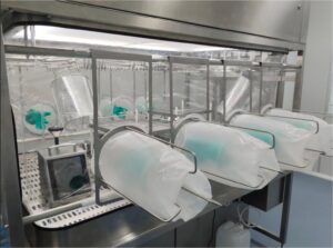
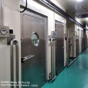
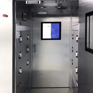
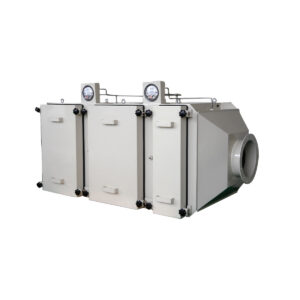
Introduction to LAF Units
The controlled environment industry has evolved tremendously over the past few decades, with Laminar Air Flow (LAF) units emerging as essential components in maintaining contamination-free workspaces. I’ve spent considerable time working with these sophisticated systems, and the precision they bring to critical environments never ceases to impress me. While many see them simply as “clean air machines,” LAF units represent decades of engineering refinement specifically designed to protect sensitive processes, products, and research.
LAF units function on a fundamentally different principle than standard air filtration systems. Rather than merely filtering air, they create a unidirectional, particle-free environment where air molecules move in parallel lines at uniform velocity. This critical distinction prevents the turbulent mixing that can reintroduce contaminants into clean workspaces.
The concept took shape in the 1960s when semiconductor manufacturing demanded unprecedented cleanliness levels. Today, these systems have become indispensable across pharmaceuticals, biotechnology, electronics, and research laboratories. What’s particularly fascinating is how the basic principle remains unchanged despite significant technological advancements in materials, control systems, and energy efficiency.
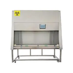
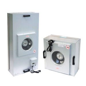
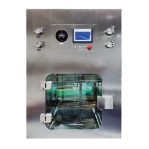
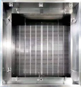
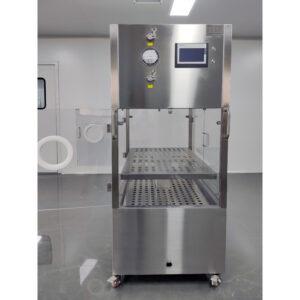
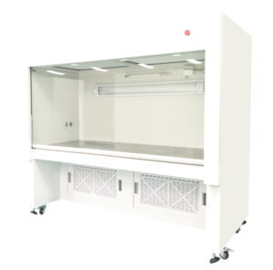
At its core, a LAF unit comprises several key components: a fan system, HEPA or ULPA filters, a plenum for airflow distribution, and a precisely engineered cabinet structure. Together, these elements work in harmony to achieve particle counts often measured in the single digits per cubic foot of air—a level of cleanliness that’s difficult to comprehend until you’ve witnessed it firsthand.
The applications have expanded far beyond their original intent. From protecting cell cultures in research labs to ensuring sterility in pharmaceutical compounding, these systems have become the standard wherever airborne contamination presents a risk. This adaptability partially explains why the global market for cleanroom equipment continues its upward trajectory.
How LAF Units Work: The Science Behind Clean Air
What makes LAF technology particularly effective is the carefully engineered airflow pattern. Unlike conventional air handling systems where air moves turbulently—swirling and mixing unpredictably—laminar flow creates parallel streamlines of air that move in a single direction at uniform speed. This unidirectional flow essentially “sweeps” particles away from the protected area rather than recirculating them.
The physics behind this process fascinates me. When air moves turbulently, particles can get caught in eddies and vortices, eventually settling on surfaces. In contrast, laminar flow creates what engineers call a “piston effect”—pushing contaminants in one direction without allowing them to return. This fundamentally changes how we approach contamination control.
The workhorse of any LAF unit is its filtration system. Most units employ High-Efficiency Particulate Air (HEPA) filters, which must capture at least 99.97% of particles 0.3 microns in diameter—about 300 times smaller than the width of a human hair. Some advanced applications utilize Ultra-Low Penetration Air (ULPA) filters, which capture 99.9995% of particles 0.12 microns and larger.
“The efficiency rating of HEPA filters often confuses newcomers to the field,” notes Dr. Jennifer Campos, a cleanroom certification specialist I consulted. “People assume the 0.3-micron specification means larger particles might slip through, but that’s actually the ‘most penetrating particle size’—both smaller and larger particles are captured with even greater efficiency due to diffusion and interception mechanisms.”
The technical design requires precise balancing of several factors:
| Design Factor | Importance | Considerations |
|---|---|---|
| Air Velocity | Critical for maintaining laminar flow | Typically 90 ± 20 feet per minute (0.45 ± 0.1 m/s) for horizontal flow units |
| Plenum Design | Ensures uniform air distribution | Must minimize turbulence and dead spots |
| Filter Sealing | Prevents bypass leakage | Gasket materials must be compatible with cleanroom requirements |
| Workspace Geometry | Affects airflow patterns | Smooth surfaces without obstructions optimize laminar conditions |
The fan system that powers this process must deliver consistent pressure while minimizing vibration and noise. Modern LAF units from YOUTH Tech incorporate EC (electronically commutated) motors that provide precise control while reducing energy consumption—an important advancement over earlier designs that used less efficient motor types.
The entire system operates under positive pressure, meaning air constantly flows outward from the clean zone. This prevents room air (with its relatively higher particle count) from entering the protected workspace. It’s this combination of positive pressure, unidirectional flow, and ultra-efficient filtration that creates a work environment virtually free of airborne contaminants.
Types of LAF Units and Their Applications
The diversity of LAF units available today reflects their widespread adoption across industries. Two fundamental configurations dominate the market: horizontal and vertical flow units, each with distinct advantages depending on the application.
Horizontal flow units direct filtered air across the work surface parallel to the bench. This design excels in applications where products need protection from operator-generated contamination. I’ve found them particularly effective in electronics assembly, where components are sensitive to human-sourced particles. The air flows from the back of the unit toward the operator, carrying potential contaminants away from the work.
Vertical flow units, by contrast, direct air downward onto the work surface. These are favored in applications requiring maximum product protection, such as aseptic pharmaceutical processing. During a facility upgrade project I managed last year, we selected vertical units specifically because they minimize the chance of operator-generated particles reaching critical products.
The choice between these configurations isn’t trivial—it fundamentally affects how work must be performed within the unit. As cleanroom consultant Michael Levine explained to me, “The most sophisticated LAF unit will fail if operators don’t understand and work with the airflow pattern rather than against it. This is why proper training is as important as the equipment itself.”
Beyond basic flow direction, LAF units vary considerably in size and mobility:
| Type | Typical Dimensions | Best Applications | Considerations |
|---|---|---|---|
| Benchtop Units | 2-4 ft wide | Small-scale laboratory work, PCR setup | Limited workspace but highly portable |
| Full-sized Cabinets | 4-8 ft wide | Pharmaceutical compounding, Quality control testing | Greater workspace but requires dedicated floorspace |
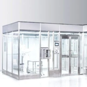
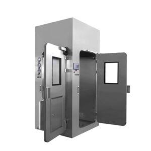
| Modular Cleanrooms | Custom dimensions | Complete production lines, Larger assembly operations | Highest capacity but significant installation requirements |
| Mobile Units | Varies | Temporary clean environments, Field service | Compromise between portability and performance |
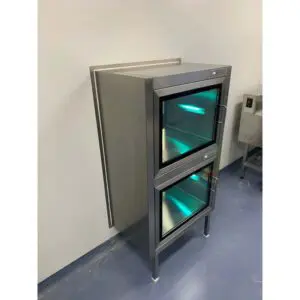
Industry-specific adaptations further expand these configurations. Pharmaceutical applications often incorporate additional features like UV germicidal lamps for surface decontamination between operations. Semiconductor manufacturing frequently requires specialized laminar air flow units with ultra-precise temperature control to prevent thermal expansion issues during nanoscale fabrication.
What’s particularly interesting is how the fundamental principles remain consistent across these variations. Whether directing air horizontally across a circuit board assembly or vertically onto a sterile pharmaceutical preparation, the goal remains the same: particle-free, unidirectional airflow that prevents contamination.
Key Components and Technical Specifications
The performance of any LAF unit ultimately depends on the quality and integration of its components. Understanding these elements helps both in selection and operation—something I wish I’d known before specifying equipment for our first cleanroom expansion.
The heart of every LAF unit is its filtration system. While HEPA filters represent the minimum standard, their specific classification significantly affects performance:
| Filter Class | Efficiency (at MPPS*) | Typical Applications | Relative Cost |
|---|---|---|---|
| H13 | 99.95% | General cleanroom work, ISO 7-8 environments | Baseline |
| H14 | 99.995% | Pharmaceutical processing, ISO 5-6 environments | 25-40% higher |
| ULPA (U15) | 99.9995% | Semiconductor manufacturing, Advanced research | 50-80% higher |
| *MPPS = Most Penetrating Particle Size |
Beyond filtration, the airflow characteristics determine a unit’s effectiveness. Engineers measure airflow velocity across the workspace, typically targeting 90 feet per minute (0.45 m/s) for horizontal flow units and 60-80 feet per minute (0.30-0.40 m/s) for vertical units. This seemingly minor distinction can dramatically affect both particle control efficiency and operator comfort.
“Too slow, and you risk inadequate particle removal; too fast, and you create turbulence that defeats the purpose of laminar flow,” explains Dr. Sarah Chen, a cleanroom design specialist. “Finding that balance requires precise engineering and careful testing.”
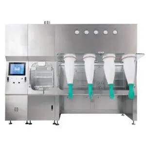
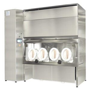
The construction materials deserve careful consideration as well. Stainless steel dominates in pharmaceutical and medical applications due to its chemical resistance and cleanability. For electronics manufacturing, where electrostatic discharge (ESD) concerns exist, specialized conductive materials often replace standard stainless steel.
Control systems have evolved significantly in recent years. Basic units still employ simple on/off switches with manual speed controls, but advanced LAF units now feature digital interfaces with integrated monitoring capabilities. These systems can track filter life, airflow parameters, and even particle counts in real-time—providing both operational assurance and documentation for regulatory compliance.
Power consumption represents an often overlooked specification. Traditional units can draw significant electricity, especially when operated continuously. During our facility expansion, we were surprised when an electrical assessment revealed we needed to upgrade service panels to accommodate the additional load. Newer energy-efficient designs with EC motors and optimized airflow paths can reduce consumption by 30-50% compared to older models.
Workspace dimensions ultimately determine operational capacity. Standard widths range from 2 to 8 feet, with depths typically between 2 and 4 feet. The effective working height—the distance between the work surface and the filter face or airflow barrier—generally falls between 12 and 30 inches. These parameters must align with both operational requirements and facility constraints.
Installation and Setup Requirements
Installing a LAF unit involves considerably more planning than simply placing equipment and plugging it in. I learned this lesson the hard way during my first cleanroom project, when we discovered—after delivery—that our ceiling height couldn’t accommodate the vertical flow unit we’d selected.
Pre-installation site assessment should verify several critical factors:
- Spatial dimensions and clearances
- Floor loading capacity for larger units
- Electrical service availability (voltage, phase, and amperage)
- Ambient environmental conditions (temperature, humidity, existing particulate levels)
- Access routes for equipment delivery
Room preparation often requires modifications beyond what’s initially anticipated. Vinyl or epoxy flooring may need installation to reduce particulate generation. Walls might require non-shedding paint or paneling. Even ceiling tiles may need replacement with cleanroom-compatible versions in adjacent areas.
During a pharmaceutical facility upgrade I managed, we discovered that vibration from adjacent HVAC equipment was affecting airflow patterns in our newly installed LAF units. We ultimately needed to add isolation mounting systems—an expense and delay that proper preliminary assessment would have identified.
Utility connections vary by model but typically include dedicated electrical circuits. Some advanced units may require compressed air, vacuum connections, or data network access for monitoring systems. Additionally, units with built-in exhaust systems may need ducting to remove filtered air or process vapors.
The physical installation should be performed by qualified personnel familiar with cleanroom equipment. Improper handling can damage filters or misalign critical components. I’ve witnessed the consequences of rushed installations—from damaged filter media to improperly sealed housings that allowed unfiltered air to bypass the filtration system entirely.
Once installed, every laminar flow unit requires comprehensive testing and certification before use. This process typically includes:
- Filter integrity testing (using DOP or PAO aerosol challenge)
- Airflow velocity mapping across the workspace
- Particle count verification
- Smoke pattern visualization to confirm laminar flow characteristics
This certification process isn’t merely procedural—it provides baseline performance data crucial for ongoing monitoring. The commissioning documentation should be preserved as part of the unit’s validation package, especially in regulated environments.
Integration with existing cleanroom systems requires careful planning. LAF units supplement but don’t replace room-level environmental controls. The interaction between room air handling systems and LAF units can create unexpected airflow patterns if not properly coordinated. In some cases, dedicated make-up air systems may be needed to compensate for the air volume processed by multiple LAF units.
Maintenance and Performance Optimization
The effectiveness of any LAF unit degrades over time without proper maintenance. This reality became painfully clear to me when particle counts inexplicably rose in our quality control lab—a situation ultimately traced to deferred maintenance on an aging LAF unit.
A comprehensive maintenance program should include these key elements:
| Maintenance Task | Frequency | Purpose |
|---|---|---|
| Surface cleaning | Daily | Removes accumulated particles from work surfaces |
| Pre-filter inspection/replacement | Monthly | Prevents premature loading of main HEPA filter |
| Airflow velocity verification | Quarterly | Confirms consistent performance within specifications |
| Complete recertification | Annually | Validates overall system integrity and performance |
| Main filter replacement | As needed (typically 3-5 years) | Ensures continued filtration efficiency |
Filter replacement deserves special attention as it represents both a significant expense and a critical performance factor. Rather than following rigid calendar-based schedules, I’ve found differential pressure monitoring provides a more accurate indication of filter loading. Most modern LAF units include pressure gauges or digital monitoring for this purpose.
The replacement process itself requires careful planning and execution. During a recent filter change in our cell culture facility, we established a detailed protocol involving:
- Scheduling during facility downtime
- Thorough cleaning of the surrounding area
- Controlled removal of old filters to prevent contamination
- Careful installation of new filters with proper gasketing
- Post-installation testing and certification
- Documentation of all work performed
Beyond routine maintenance, performance optimization can significantly extend filter life and improve energy efficiency. Simple operational adjustments like running at reduced speed during non-critical periods can yield substantial energy savings. During off-hours at our facility, we program units to operate at 70% of standard velocity, which reduced energy consumption by approximately 40% during those periods.
Environmental factors significantly impact performance and maintenance requirements. Higher ambient particle counts accelerate filter loading. Humidity extremes can affect filter media integrity. Even temperature fluctuations can influence airflow patterns. Monitoring these conditions helps explain performance variations and informs maintenance scheduling.
Troubleshooting skills develop with experience, but common issues include:
- Uneven airflow (often caused by filter loading or damaged filter media)
- Excessive noise (typically fan bearing issues or vibration transfer)
- Inadequate particulate control (possibly filter bypass or compromised seals)
- Control system malfunctions (frequently related to sensor calibration)
Documentation of all maintenance activities is essential, particularly in regulated environments. These records provide evidence of proper system care and help identify developing issues through trend analysis. Our quality system now includes comprehensive maintenance logs for each LAF unit, accessible through QR codes mounted on the equipment.
Regulatory Standards and Compliance
The regulatory landscape surrounding LAF units varies significantly by industry and application. This complexity can be overwhelming—I recall spending weeks deciphering requirements when establishing our pharmaceutical compounding operation.
ISO 14644 standards provide the foundational framework for cleanroom and controlled environment classification. While not specifically focused on LAF units, these standards establish the particle count limits that LAF systems must help maintain:
| ISO Class | Maximum Particles/m³ (≥0.5μm) | Typical Applications |
|---|---|---|
| ISO 5 (Class 100) | 3,520 | Aseptic processing, Critical operations |
| ISO 6 (Class 1,000) | 35,200 | Medical device assembly, Less critical pharma ops |
| ISO 7 (Class 10,000) | 352,000 | General manufacturing, Component preparation |
| ISO 8 (Class 100,000) | 3,520,000 | Packaging, Less critical operations |
Industry-specific regulations add further requirements. Pharmaceutical operations must comply with FDA regulations (21 CFR Parts 210/211 in the US) or EU GMP Annex 1 for sterile manufacturing. These regulations address not just the performance specifications but also validation, monitoring, and documentation requirements.
“The key distinction many facilities miss is between equipment capability and operational compliance,” notes regulatory consultant Rebecca Torres. “Your LAF unit might meet technical specifications perfectly, but without proper procedural controls and documentation, you’ll still fail regulatory scrutiny.”
This observation resonates with my experience. During an FDA inspection, our technically compliant equipment wasn’t questioned—but our incomplete maintenance records triggered several observations requiring corrective action.
Certification requirements vary by application but typically follow industry standards like IEST-RP-CC002 (Unidirectional Flow Clean-Air Devices). These procedures verify:
- Filter integrity using aerosol photometer testing
- Airflow velocity and uniformity
- Particle counting in the workspace
- Smoke pattern testing to visualize airflow characteristics
Documentation requirements extend well beyond certification records. A comprehensive quality system for LAF units typically includes:
- Installation qualification (IQ) documenting proper installation
- Operational qualification (OQ) verifying performance to specifications
- Performance qualification (PQ) confirming suitability for specific processes
- Standard operating procedures for use and maintenance
- Operator training records
- Routine monitoring logs
- Maintenance and service records
- Calibration certificates for monitoring instruments
Meeting these requirements demands significant resources, but the consequences of non-compliance can be severe—from regulatory actions to compromised product quality. In highly regulated industries, third-party certification by qualified professionals provides an additional layer of compliance assurance.
Future Trends and Innovations in LAF Technology
The basic principles of laminar airflow have remained remarkably consistent over decades, but technological advancements continue to enhance efficiency, monitoring capabilities, and sustainability. Having followed these developments closely, I’m particularly excited about several emerging trends.
Energy efficiency has become a primary focus as facilities seek to reduce operating costs and environmental impact. Traditional LAF units consume substantial electricity when operated continuously. Newer designs incorporate several innovations:
- EC (electronically commutated) motor technology reducing power consumption by 30-60%
- Variable frequency drives allowing precise airflow adjustment based on need
- Advanced plenum designs optimizing airflow paths to reduce resistance
- “Smart” operation modes that modify performance based on actual use patterns
During a recent facility energy audit, we calculated that replacing our older LAF units with newer energy-efficient models would provide a return on investment in less than three years through electricity savings alone—while also reducing our carbon footprint.
Remote monitoring capabilities have transformed how facilities manage these critical systems. Modern units incorporate sensors tracking:
- Filter differential pressure
- Airflow velocity
- Power consumption
- Operating hours
- Environmental conditions (temperature, humidity)
- In advanced systems, actual particle counts
These parameters can now feed into building management systems or dedicated monitoring platforms, enabling real-time performance verification and predictive maintenance. When participating in a beta test of this technology, I was impressed by the system’s ability to detect subtle performance changes well before they became problematic.
Sustainable design approaches are gaining traction as environmental considerations become more prominent. Manufacturers are exploring:
- Filter media with extended service life
- Materials with lower environmental impact
- Designs facilitating component recycling
- Reduced use of potentially harmful substances like adhesives and solvents
These sustainability initiatives align with broader industry trends toward “green” laboratory and manufacturing practices. While sometimes carrying higher initial costs, these approaches often deliver long-term operational savings while reducing environmental impact.
Emerging applications continue to expand the reach of LAF technology. Recent implementations include:
- Protected environments for advanced 3D bioprinting
- Contamination control for quantum computing component manufacturing
- Specialized units for gene therapy production
- Portable systems for field deployment in global health initiatives
Dr. Michael Jensen, a cleanroom design innovator I spoke with recently, believes we’re entering a new era of application-specific designs: “The future isn’t about making LAF units bigger or more powerful—it’s about tailoring airflow characteristics, monitoring capabilities, and form factors to highly specific process requirements. We’re moving from general-purpose equipment to precision tools.”
This evolution will likely accelerate as manufacturing processes become increasingly sensitive to microscale and nanoscale contamination. The requirements for advanced semiconductor nodes, cell and gene therapies, and quantum technologies far exceed what was considered “clean” just a decade ago.
Integration with robotic and automated systems represents another significant trend. As manual operations increasingly give way to automation, LAF units are being designed to accommodate robotic arms, conveyor systems, and other mechanical handling equipment while maintaining proper airflow patterns.
Selecting the Right LAF Unit for Your Application
Choosing the appropriate LAF system involves balancing technical requirements, operational needs, and budget constraints. Through years of specifying and implementing these systems, I’ve developed a methodical approach to this decision process.
The first step involves thoroughly defining your application requirements:
- Required cleanliness level (ISO classification or particle count specification)
- Process sensitivity to specific contaminant types (particles, microorganisms, etc.)
- Physical dimensions of materials and equipment used within the workspace
- Workflow patterns and operator ergonomic requirements
- Integration with existing facilities and systems
These foundational requirements narrow the field of potential options before considering secondary factors like energy efficiency and advanced features.
Flow direction represents a primary decision point. Horizontal flow units excel where operators need access to materials without reaching through the clean airstream. Vertical flow units provide superior protection for processes where contaminants from above would be problematic. Some applications benefit from hybrid designs combining elements of both approaches.
During a medical device manufacturing project, we initially specified horizontal flow units based on comparable installations elsewhere. After conducting workflow analysis, however, we realized vertical units better accommodated our specific assembly process and operator movement patterns. This adjustment, while delaying implementation by several weeks, ultimately improved both ergonomics and contamination control.
Size and configuration options span a wide spectrum:
| Configuration | Typical Work Area | Best For | Limitations |
|---|---|---|---|
| Benchtop | 2-4′ wide × 2′ deep | Small-scale operations, limited space | Restricted workspace, sometimes awkward ergonomics |
| Console | 4-6′ wide × 2-3′ deep | General laboratory work, standard manufacturing | Fixed location, moderate capacity |
| Walk-in/Booth | 6-12’+ wide × variable depth | Large equipment, multi-operator processes | Significant footprint, higher operating costs |
| Custom | Variable | Specialized equipment, unique processes | Higher cost, longer lead times, limited standardization |
Budget considerations extend beyond initial purchase price. A comprehensive cost assessment should include:
- Installation expenses (often 10-30% of unit cost)
- Utility requirements and ongoing energy costs
- Certification and validation expenses
- Consumables (pre-filters, etc.)
- Maintenance requirements
- Expected service life and eventual replacement
When evaluating options for our cell culture facility expansion, we found that units with 40% higher purchase prices offered 30% lower energy consumption and extended filter life—resulting in lower total cost of ownership despite the higher initial investment.
Vendor selection factors include not just equipment specifications but also:
- Local service capability
- Spare parts availability
- Technical support resources
- Previous installation references
- Company stability and longevity
- Validation documentation quality
For critical applications, I strongly recommend visiting reference installations to observe similar units in operation. During one such visit, I discovered noise levels much higher than anticipated—information that prompted design modifications before our purchase.
Advanced features worth considering include:
- Digital monitoring and control systems
- Data logging capabilities
- Remote monitoring options
- Programmed operation modes
- Integration with facility management systems
- Energy-saving technologies
The selection process culminates in a detailed specification that becomes part of your purchase agreement. This document should define not just the equipment itself but also acceptance criteria, validation requirements, documentation deliverables, and support expectations.
By methodically working through these considerations, you’ll significantly improve your chances of selecting a LAF unit that meets both immediate needs and long-term requirements. The investment in thorough evaluation pays dividends through improved performance, reduced operating costs, and fewer operational disruptions.
Conclusion: Maximizing Value from Your LAF Investment
Laminar airflow technology represents a significant investment in product quality, process consistency, and regulatory compliance. Throughout this comprehensive LAF Unit Guide, we’ve explored the critical aspects of selection, implementation, and operation of these sophisticated systems.
The return on this investment depends largely on proper implementation and ongoing management. Having overseen multiple cleanroom projects of varying scales, I’ve observed that successful facilities treat their LAF units as process-critical assets rather than simply pieces of equipment. This mindset drives appropriate resource allocation for maintenance, monitoring, and periodic upgrades.
Training remains one of the most frequently overlooked aspects of LAF implementation. Even perfectly designed and maintained units will fail to deliver expected performance if operators don’t understand proper work techniques. Comprehensive training should cover not just operational procedures but also the underlying principles of laminar flow, contamination sources, and the impact of specific behaviors on environmental control.
The regulatory landscape continues to evolve, with increasing emphasis on risk-based approaches to contamination control. Rather than focusing exclusively on technical specifications and test results, forward-thinking organizations are implementing comprehensive contamination control strategies that consider process requirements, facility design, equipment capabilities, and human factors holistically.
While technology advances, the fundamental principles of contamination control through laminar airflow remain unchanged. Whether you’re implementing your first LAF unit or upgrading an existing facility, attention to these core principles will serve you well.
For those considering a LAF unit acquisition, I encourage thorough evaluation of your process requirements, careful vendor selection, and comprehensive planning for implementation. The difference between adequate and excellent performance often lies in these preparatory steps rather than in the equipment itself.
For organizations with existing installations, regular performance review and comparison against current best practices can identify improvement opportunities. The field continues to evolve, and yesterday’s state-of-the-art approach may no longer represent optimal practice.
As we look toward the future, laminar airflow technology will continue to play a critical role in industries where contamination control is essential. The integration of advanced monitoring capabilities, improved energy efficiency, and enhanced usability will make these systems increasingly effective and accessible. Those who understand both the fundamental principles and emerging capabilities will be best positioned to leverage this technology for competitive advantage.
Frequently Asked Questions of LAF Unit Guide
Q: What is a LAF Unit and how does it work in a cleanroom environment?
A: A LAF (Laminar Air Flow) unit is a device that uses HEPA filtered air to provide a clean environment, typically in Class 5 conditions. It works by creating a smooth, linear flow of air that minimizes turbulence and contamination, making it ideal for aseptic handling in industries like pharmaceuticals and biotech.
Q: What types of LAF Units are available, and how are they implemented?
A: LAF Units come in various forms, such as mobile, ceiling-mounted, and self-standing. They can be placed above devices or specifically designed for customers’ needs. Some can even eliminate the need for a full cleanroom, like Straddle LAFs for large-scale operations.
Q: How do LAF Units differ from other types of airflow systems like RABS?
A: LAF Units primarily focus on protecting open materials with vertical laminar airflow, providing Class 5 conditions. RABS (Restricted Access Barrier Systems) also use HEPA filtered air but focus on the critical line where substances and packaging are exposed, providing comprehensive protection against contamination by washing the area with unidirectional airflow.
Q: What are the benefits of using a LAF Unit in the pharmaceutical industry?
A: LAF Units offer several benefits in the pharmaceutical industry:
- Contamination Control: They prevent airborne contamination, ensuring aseptic processing.
- Consistency: Provide a reliable environment with consistent output quality.
- Maintenance: Easy to test and maintain.
Q: How often should a LAF Unit be cleaned and qualified?
A: LAF Units require regular maintenance to ensure their effectiveness. Prefilters should be cleaned every three months, and the entire system should be qualified every six months. Cleaning and qualification are crucial to maintaining the required air cleanliness standards.
Q: Can LAF Units be customized for specific applications?
A: Yes, LAF Units can be customized to meet specific needs across various industries, including healthcare and biopharmaceuticals. They can be configured to accommodate unique requirements, such as housing robotic machinery for aseptic processes.
External Resources
LAF Unit Specifications – This document provides detailed specifications for LAF units, including their application in maintaining clean environments.
SOP for Operation of Laminar Air Flow – Offers a standard operating procedure for the operational maintenance of laminar airflow units.
SOP for LAF Unit in Sampling Room – Provides guidelines for operating and cleaning LAF units in sampling rooms.
The Essential Guide to HEPA Filters in LAF Units – Discusses the importance and operation of HEPA filters within laminar airflow equipment.
Mikropor LAF Cabinets – Details the features and applications of laminar airflow cabinets designed by Mikropor.
Cleanroom Equipment for LAF – While not a specific LAF unit guide, this provides relevant information on HEPA filters commonly used in cleanroom environments, including LAF systems.
Related Contents:
- Pharma Lab Laminar Air Flow Unit Applications
- Laminar Air Flow Units for Contamination Control
- USP <797> Compliance for Laminar Units
- Horizontal vs Vertical Laminar Units 2025
- Fan Filter Units or Laminar Flow Hoods: Which to Choose?
- 5 Essential Steps to Install a LAF Unit Correctly
- Portable vs Fixed Laminar Air Flow Units
- Industrial vs Lab Laminar Air Flow Units
- LAF Units vs HEPA Filters: Which is Right for Your Facility?


