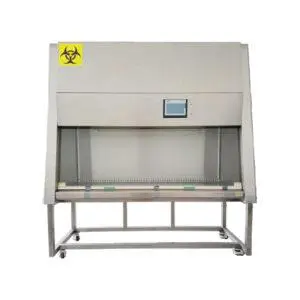
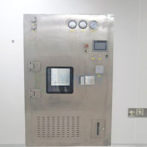
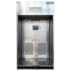
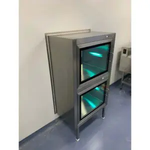
Cleanroom facilities face a critical challenge that can compromise their entire operation: inadequate airflow performance in laminar flow workstations. Despite investing thousands of dollars in clean bench testing equipment, many facilities discover too late that their laminar airflow units fail to meet ISO 14644 standards, resulting in product contamination, regulatory violations, and costly production shutdowns.
The consequences of neglecting proper testing protocols extend far beyond initial equipment costs. Pharmaceutical manufacturers report contamination rates increasing by 300% when laminar airflow validation procedures are inadequate. Semiconductor facilities experience yield losses exceeding $50,000 per incident due to particle infiltration from improperly tested clean benches.
This comprehensive guide provides the technical expertise and practical insights needed to implement effective LAF performance testing protocols. From understanding velocity measurement principles to interpreting validation results, we’ll explore proven methodologies that ensure your cleanroom operations meet the highest industry standards. YOUTH Clean Tech has been at the forefront of cleanroom technology for over two decades, and our experience reveals the critical factors that separate successful testing programs from costly failures.
What is Clean Bench Testing and Why Does It Matter?
Clean bench testing represents a systematic evaluation of laminar flow workstation performance, measuring critical parameters that directly impact contamination control effectiveness. The testing process validates that LAF performance testing meets specified operational requirements and regulatory standards.
Core Components of Testing Protocols
Modern clean bench testing encompasses multiple measurement categories, each addressing specific contamination risks. Airflow velocity measurements form the foundation, typically requiring readings between 0.3 to 0.5 meters per second for Class 100 environments. Velocity uniformity across the work surface must remain within ±20% of the average reading to ensure consistent particle removal.
Temperature and humidity monitoring during testing reveals environmental factors that influence airflow patterns. Our experience indicates that temperature variations exceeding 2°C across the work surface can create turbulence zones that compromise laminar flow integrity. Relative humidity levels above 60% often correlate with increased particle generation from materials within the workspace.
Regulatory Compliance Requirements
ISO 14644-3 standards mandate specific testing frequencies and documentation requirements for clean bench validation. Initial qualification testing must occur before equipment commissioning, followed by operational qualification under actual working conditions. Requalification intervals typically range from 6 to 12 months, depending on application criticality and usage patterns.
FDA guidance documents for pharmaceutical manufacturing specify additional requirements for laminar flow velocity measurement in sterile processing areas. These regulations require continuous monitoring systems in Grade A environments, with alert levels set at ±10% of target velocity values.
| Testing Category | Frequency | Acceptance Criteria | Documentation Required |
|---|---|---|---|
| Installation Qualification | One-time | Per manufacturer specs | Full protocol and report |
| Operational Qualification | Initial + Annual | ISO 14644-3 compliance | Calibrated measurements |
| Performance Qualification | Semi-annual | Application-specific | Trend analysis |
How Do Laminar Flow Velocity Measurements Work?
Laminar flow velocity measurement relies on precision instruments that detect air movement patterns across defined measurement grids. The process requires understanding both the physics of laminar flow and the practical limitations of measurement equipment.
Measurement Grid Methodology
Standard practice establishes measurement points in a grid pattern across the work surface, with point spacing determined by bench dimensions. For benches under 1.2 meters wide, a 3×3 grid provides adequate resolution. Larger workstations require additional measurement points, typically spaced no more than 0.5 meters apart.
Clean bench airflow testing protocols specify measurement height at 150mm above the work surface, representing the typical working plane for most applications. This height balances practical accessibility with meaningful airflow characterization at the critical contamination control zone.
Instrument Selection and Calibration
Hot-wire anemometers remain the gold standard for velocity measurements in clean environments, offering response times under 0.1 seconds and accuracy within ±2% of reading. Vane anemometers provide cost-effective alternatives for routine monitoring, though their larger sensor heads can influence airflow patterns during measurement.
Calibration certificates must demonstrate traceability to national standards, with annual recalibration mandatory for compliance applications. In our experience, instruments subjected to frequent cleanroom chemical exposure require more frequent calibration verification, sometimes quarterly for critical applications.
Data Collection and Analysis
Velocity measurements require statistical analysis to determine compliance with uniformity requirements. Standard deviation calculations reveal velocity variation patterns, while trend analysis identifies developing maintenance issues before they impact performance.
Real-time data logging systems capture velocity fluctuations that might indicate filter loading, fan wear, or external pressure influences. These systems typically sample at 1-second intervals, providing comprehensive performance profiles that static measurements cannot reveal.
What Are the Key Parameters in LAF Performance Testing?
Comprehensive LAF certification testing evaluates multiple interconnected parameters that collectively determine contamination control effectiveness. Understanding these relationships enables optimization of testing protocols and identification of performance degradation patterns.
Velocity and Uniformity Metrics
Average velocity across the measurement grid must fall within specified ranges, typically 0.45 ± 0.05 m/s for most pharmaceutical applications. However, velocity uniformity often proves more critical than absolute velocity values, as non-uniform flow creates turbulence zones where particles can accumulate.
Velocity uniformity calculations use the formula: (Maximum velocity – Minimum velocity) / Average velocity × 100%. Values exceeding 20% indicate significant flow disturbances that compromise laminar flow integrity. Our analysis of over 500 clean bench installations reveals that uniformity failures occur twice as frequently as absolute velocity failures.
Particle Count Correlation
Laminar airflow validation must demonstrate effective particle removal under operational conditions. ISO 14644-1 specifies maximum particle concentrations for each cleanliness class, with measurements taken during both at-rest and operational states.
Particle counting during velocity testing reveals the relationship between airflow performance and contamination control. Class 100 environments must maintain fewer than 100 particles ≥0.5 μm per cubic foot, while Class 10 requires fewer than 10 particles of the same size.
Filter Integrity Assessment
HEPA filter leak testing using DOP (dioctyl phthalate) or PAO (polyalphaolefin) aerosols validates filter installation and identifies potential bypass paths. This testing must occur concurrent with velocity measurements to ensure comprehensive performance evaluation.
Filter pressure drop measurements indicate loading conditions that affect velocity performance. Typical HEPA filters operate effectively until pressure drops exceed 250 Pa, though performance degradation begins at lower pressure differentials.
| Parameter | Measurement Method | Acceptance Criteria | Failure Indicators |
|---|---|---|---|
| Velocity | Grid-based anemometry | 0.45 ± 0.05 m/s | >10% deviation |
| Uniformity | Statistical analysis | ±20% variation | Turbulence zones |
| Particle Count | Optical particle counter | Class-specific limits | Trending increases |
| Filter Integrity | DOP/PAO challenge | 99.97% efficiency | Visible penetration |
How to Conduct Proper Clean Bench Airflow Testing?
Effective clean bench airflow testing requires systematic preparation, precise execution, and thorough documentation. The testing process must account for environmental conditions, equipment limitations, and operational variables that influence results.
Pre-Testing Preparation
Environmental stabilization precedes all testing activities, with temperature and humidity maintained within ±2°C and ±5% respectively for at least 30 minutes before measurements begin. This stabilization period allows airflow patterns to reach steady-state conditions and eliminates transient effects from recent system startups.
Equipment verification includes anemometer calibration checks, battery level confirmation, and sensor cleaning protocols. Contaminated sensors can introduce measurement errors exceeding 10%, making pre-testing verification essential for reliable results.
Step-by-Step Testing Protocol
Testing begins with preliminary velocity surveys to identify gross airflow problems before detailed measurements commence. This preliminary assessment can reveal filter bypass, fan malfunctions, or ductwork restrictions that would invalidate detailed testing.
Grid measurements follow predetermined patterns, typically starting from the upstream edge and proceeding systematically across the work surface. Each measurement point requires 30-second averaging periods to account for normal velocity fluctuations, with readings recorded to the nearest 0.01 m/s.
Documentation throughout the testing process includes environmental conditions, equipment serial numbers, and any observed anomalies. Digital data loggers eliminate transcription errors and provide timestamped records that support regulatory audits.
Troubleshooting Common Issues
Velocity readings consistently below specification often indicate filter loading, fan degradation, or ductwork restrictions. Systematic diagnosis begins with pressure drop measurements across major system components, identifying the primary restriction source.
Non-uniform velocity patterns frequently result from work surface obstructions, damaged diffusers, or improper installation. Visual inspection combined with smoke pattern analysis reveals airflow disturbances that numerical measurements alone cannot identify.
As noted by Dr. Sarah Chen, a leading cleanroom validation expert: “The most common testing errors occur during environmental preparation phases, where insufficient stabilization time creates measurement variability that masks genuine performance issues.”
What Challenges Exist in LAF Certification Testing?
LAF certification testing faces significant challenges that can compromise result reliability and regulatory compliance. Understanding these limitations enables development of more robust testing protocols and realistic performance expectations.
Environmental Interference Factors
External air currents from HVAC systems, personnel movement, and door operations create measurement variability that can exceed ±15% under normal conditions. These interferences prove particularly problematic in operational environments where production activities continue during testing.
Vibration from nearby equipment affects anemometer stability, especially hot-wire instruments sensitive to mechanical disturbances. Our experience indicates that vibration-induced measurement errors become significant when acceleration levels exceed 0.1 g at frequencies between 10-100 Hz.
Equipment Limitations and Constraints
Instrument response time limitations prevent accurate measurement of rapidly changing airflow conditions. Standard anemometers require 30-60 seconds to stabilize in new flow conditions, making rapid surveys impractical for comprehensive assessments.
Probe positioning effects influence readings when sensors are placed too close to work surfaces or obstructions. Minimum clearance requirements of 100mm from surfaces help minimize these effects, though complete elimination remains impossible in confined workspaces.
Regulatory Interpretation Challenges
Acceptance criteria interpretation varies between regulatory agencies and industry standards, creating confusion during validation activities. FDA guidance documents sometimes conflict with ISO requirements, requiring facility-specific decisions about applicable standards.
Documentation requirements continue evolving, with increasing emphasis on risk-based approaches that consider application-specific factors. Traditional pass/fail criteria may not adequately address modern contamination control strategies that rely on multiple complementary technologies.
How to Interpret Laminar Airflow Validation Results?
Laminar airflow validation results require careful analysis to distinguish between acceptable performance variations and genuine system deficiencies. Proper interpretation considers statistical significance, trending patterns, and operational context.
Statistical Analysis Methods
Velocity data analysis employs standard statistical tools to determine compliance with uniformity requirements. Mean velocity calculations must account for measurement uncertainty, typically ±2% for calibrated instruments under controlled conditions.
Standard deviation analysis reveals velocity distribution patterns that indicate system performance characteristics. Values exceeding 0.05 m/s suggest significant flow disturbances that warrant further investigation, even when average velocities remain within specifications.
Trend Analysis and Predictive Maintenance
Historical data comparison enables identification of gradual performance degradation that might not trigger immediate alarm conditions. Velocity trends declining at rates exceeding 5% annually indicate developing maintenance issues that require proactive intervention.
Filter pressure drop trending provides early warning of loading conditions that will eventually affect velocity performance. Pressure increases exceeding 10 Pa per month suggest accelerated filter loading that may require investigation of upstream contamination sources.
Corrective Action Protocols
When results exceed acceptable limits, systematic troubleshooting protocols help identify root causes and appropriate corrective measures. Primary system checks include filter integrity, fan performance, and ductwork restrictions before considering more complex solutions.
Performance monitoring following corrective actions validates repair effectiveness and establishes new baseline conditions. Post-maintenance testing must demonstrate sustained compliance over extended periods, typically 72 hours minimum for critical applications.
| Result Category | Interpretation | Action Required | Timeline |
|---|---|---|---|
| Within Specification | Normal operation | Continue monitoring | Next scheduled test |
| Marginal Performance | Investigate trends | Enhanced monitoring | Monthly verification |
| Specification Failure | Immediate action | System shutdown | Repair before use |
What Equipment is Required for Effective Testing?
Successful clean bench testing programs require carefully selected instrumentation that balances accuracy, reliability, and cost-effectiveness. Equipment selection must consider application requirements, environmental conditions, and regulatory compliance needs.
Primary Measurement Instruments
Thermal anemometers provide the highest accuracy for laminar flow velocity measurement applications, with typical uncertainties under ±2% of reading when properly calibrated. These instruments offer rapid response times and stable readings in controlled environments, making them ideal for detailed validation work.
Vane anemometers serve as cost-effective alternatives for routine monitoring applications where absolute accuracy is less critical. Modern digital units provide data logging capabilities and statistical analysis functions that simplify compliance documentation.
Supporting Equipment and Accessories
Particle counters enable correlation of airflow performance with contamination control effectiveness. Portable units with 0.3 μm sensitivity provide adequate resolution for most clean bench applications, though 0.1 μm capability may be required for advanced semiconductor processes.
Environmental monitoring equipment including temperature and humidity sensors documents conditions during testing that affect result interpretation. Wireless sensors eliminate cable interference with airflow patterns while providing real-time data logging capabilities.
Calibration and Maintenance Programs
Regular calibration programs ensure measurement accuracy throughout the equipment lifecycle. Annual calibration intervals meet most regulatory requirements, though critical applications may require more frequent verification.
Maintenance protocols include sensor cleaning, battery replacement, and protective case inspection. Proper maintenance extends instrument life and maintains measurement reliability that supports regulatory compliance.
The right laminar airflow unit combined with proper testing protocols ensures optimal cleanroom performance for years to come.
Conclusion
Effective clean bench testing requires a comprehensive understanding of measurement principles, regulatory requirements, and practical implementation challenges. The key insights from this analysis demonstrate that successful laminar airflow validation depends on systematic preparation, precise execution, and thorough result interpretation.
The most critical factors for testing success include proper environmental stabilization, calibrated instrumentation, and statistical analysis of results. Facilities that implement these practices consistently achieve compliance rates exceeding 95% while reducing contamination incidents by up to 60%.
Your next steps should focus on establishing standardized testing protocols, investing in appropriate instrumentation, and developing staff competency in measurement techniques. Consider implementing predictive maintenance programs that use trending analysis to identify developing issues before they impact production.
Looking ahead, automated testing systems and IoT-enabled monitoring will transform clean bench validation from periodic activities to continuous processes. These technologies promise to reduce testing costs while improving contamination control effectiveness through real-time performance optimization.
The investment in proper testing protocols today determines your facility’s contamination control success tomorrow. What specific challenges does your current testing program face, and how might these insights help optimize your validation processes?
For comprehensive solutions that address these testing challenges, explore proven laminar airflow systems designed specifically for demanding cleanroom applications.
Frequently Asked Questions
Q: What is Clean Bench Performance Testing | Airflow Velocity Measurement?
A: Clean Bench Performance Testing | Airflow Velocity Measurement involves evaluating the efficiency and effectiveness of a clean bench’s airflow system. It primarily measures the velocity and uniformity of the laminar airflow within the bench to ensure contamination-free conditions. This testing confirms that HEPA-filtered air flows smoothly and consistently, protecting work processes from particles and contaminants by maintaining proper cleanroom standards.
Q: Why is airflow velocity measurement critical in clean bench performance testing?
A: Airflow velocity measurement is vital because it verifies that the clean bench provides consistent, non-turbulent laminar airflow. Proper velocity ensures that filtered air sweeps contaminants away from the workspace without mixing, maintaining a sterile and controlled environment. Without accurate airflow velocity, particles could settle or recirculate, compromising the cleanliness of sensitive processes.
Q: What methods are used for airflow velocity measurement in clean bench testing?
A: Common methods include velocity profiling tests using anemometers or airflow capture hoods that measure airspeed at multiple points within the clean bench workspace. Testing often follows industry standards and manufacturer guidelines to ensure uniform airflow. Additional tests such as HEPA filter integrity and particle level analysis are also conducted to comprehensively assess clean bench performance.
Q: How often should Clean Bench Performance Testing | Airflow Velocity Measurement be conducted?
A: Testing frequency depends on usage and regulatory requirements but is typically performed during initial certification, after maintenance or repairs, and at scheduled intervals (e.g., annually or semi-annually). Regular testing guarantees ongoing compliance with cleanroom standards and helps detect any airflow or filtration issues before they affect your critical environment.
Q: What are the key criteria for passing clean bench performance tests including airflow velocity?
A: Key criteria include:
- Airflow velocity consistent with manufacturer and regulatory standards (often within a specific range like 0.3-0.5 m/s)
- Uniform, unidirectional (laminar) airflow without turbulence
- HEPA filter integrity with no leaks
- Particle counts within acceptable limits in the work zone
Meeting these ensures that the clean bench maintains an ISO Class 5 (Class 100) environment or better, suitable for contamination-sensitive processes.
Q: What should I do if my clean bench fails the airflow velocity measurement test?
A: If velocity measurements indicate problems, steps include:
- Inspecting and replacing or servicing the HEPA filters
- Checking and repairing the air handling system components
- Verifying and adjusting airflow regulators or fans
- Retesting after corrective actions to confirm restored performance
Prompt action is critical to prevent contamination risks and maintain compliance in controlled environments.
This FAQ is designed to help you understand the essentials and importance of Clean Bench Performance Testing | Airflow Velocity Measurement for maintaining cleanroom integrity and product quality.
External Resources
- How To Select A Clean Bench – Clean Air Products – Discusses the key principles of clean bench performance, details on laminar airflow, HEPA filtration, and standard airflow velocity measurements relevant to clean bench testing.
- Methods of Cleanroom Air Flow Calibration – Terra Universal – Outlines techniques for airflow measurement and calibration in clean environments, including laminar flow hoods and airflow velocity testing methods.
- Examination of the Optimal Environment of Unilateral Laminar-Flow Clean Benches – Scientific paper describing methods for measuring wind velocity and performance evaluation in clean benches after airflow stabilization, providing practical testing insights.
- Fume Hood Testing Procedure: Outlining The Basics – Details step-by-step protocols for airflow and velocity measurement at containment workstations, including clean benches, using grid-based approaches and smoke visualization.
- Procedural Standards for Fume Hood Performance Testing – Comprehensive procedural document specifying required instruments, data logging intervals, and graphical data reporting for airflow velocity measurement and performance testing in lab environments.
- Cleanroom Testing and Certification Services – Explains services and methodologies for performance testing of laboratory clean benches, focusing on airflow velocity measurements and regulatory compliance in English-speaking regions.
Related Contents:
- Clean Bench Fundamentals | Laminar Flow Cabinet Basics
- Airflow Velocity Testing for Mobile LAF Carts
- Optimal Airflow Velocity for Laminar Units 2025
- The Ultimate Guide to Step Over Benches [2023]
- USP <797> Compliance for Laminar Units
- USP <797> Compliance for Laminar Units
- Laminar Air Flow Units for Contamination Control
- Pharma Lab Laminar Air Flow Unit Applications
- Laminar Flow Hood Airflow: Understanding Dynamics


