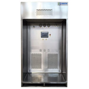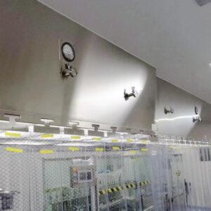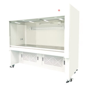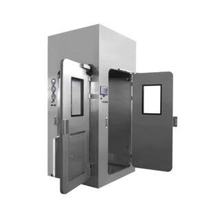
An LAF RFQ airflow controls and alarms schedule should specify the measured variable and its sensing point, the control mode and who can change it, a named alarm for each distinct condition, and a defined response to power loss and restoration. These four items together determine whether operators receive actionable information at the work zone and whether the installed equipment can be tested against the same conditions at both factory and site.
Ask what the unit actually measures
The airflow signal driving the display and any downstream alarm is not automatically the variable that describes conditions at the work zone.
A laminar airflow unit can present fan status, fan speed, a velocity derived from an anemometer at a fixed sensing point, or a pressure differential across the filter. Each signal answers a different question. Fan status tells you the motor is running. Fan speed, expressed as a percentage of maximum or as a frequency drive setting, tells you the control input but not the resulting air condition at the work zone—filter loading, duct resistance and ambient conditions can all shift the relationship between speed and delivered velocity over time. A measured velocity at a defined sensing point tells you what the air is doing at that location. Filter differential pressure tells you the resistance across the filter media, which is a maintenance indicator for that filter arrangement, not a direct statement about airflow at the work zone.
When two proposals each show a fan switch and a numeric airflow display, the displayed values can appear equivalent while answering entirely different questions. Ask each bidder to name the airflow variable, the sensing point and location, the displayed units, and the normal operating mode. Also ask them to identify any value that is inferred from fan speed rather than measured at the zone. The gap between an inferred and a measured signal becomes significant when airflow deteriorates gradually—a speed-derived reading can hold steady while actual zone velocity has fallen.
Compare the offered airflow control modes
The control mode determines whether the unit maintains a condition or simply sets an input, and that distinction shapes how the alarm schedule is written and what qualification testing can demonstrate.
A fixed fan setting runs the motor at a predetermined point. No feedback loop adjusts output in response to changing conditions. If filter resistance increases with loading or ambient pressure changes, delivered velocity shifts without any automatic correction and without a fault signal unless a separate measured alarm is configured. This mode is straightforward to test: the qualified setting is a fixed parameter, and the alarm is tied to a separately measured variable.
Automatic adjustment—often called constant velocity or constant airflow control—uses a feedback signal from a sensor at the zone or duct to continuously correct fan speed. The fan speed is the output, not the setpoint. The setpoint is the measured condition. This mode can compensate for gradual filter loading within the fan’s available range, but it also means that a fan running at or near its maximum and still unable to reach the setpoint is a fault condition, not a normal operating point. The system should indicate when it cannot maintain the requested condition; require the bidder to describe how that is communicated.
A manually adjustable control allows an operator to change the fan speed setting. This mode raises a governance question: who is authorized to change the setting, how is the change recorded, and does a change require re-qualification? Ask the bidder to identify the proposed mode, the feedback signal if one is used, who can change settings and by what mechanism, and how the system signals that it cannot maintain the requested condition. State in the RFQ which operating mode will be treated as the qualified condition against which all options are compared, so bids remain on a common basis.
Write an alarm schedule operators can use
| Condition | What to request | What to demonstrate |
|---|---|---|
| Low airflow | Measured variable and sensing point, setting owner, any justified delay, local warning and remote destination if required | Show that loss of the measured airflow condition produces the specified warning. |
| Sensor fault | A distinct indication and the expected acknowledgment and reset behavior | Show how a lost or faulty reading differs from a normal operating value. |
| Filter differential pressure indication | The sensing arrangement and the basis for the maintenance indication or any associated setting | Identify the filter indication separately from the low-airflow alarm. |
An alarm schedule is actionable when each entry names a specific condition, identifies the signal that detects it, and distinguishes that condition from every other state the system can present.
Filter differential pressure and low airflow are related but distinct signals, and they belong on separate lines in the RFQ. Filter differential pressure monitors the resistance across the filter media and rises as the filter loads. It is a maintenance indicator for the filter arrangement—it tells maintenance that the filter is approaching a service threshold. A low-airflow warning is tied to the measured operating condition at the work zone. One is not a substitute for the other: a filter can show acceptable differential pressure while a blockage or fan fault elsewhere has reduced zone velocity, and a filter can show high differential pressure while the fan is still delivering the specified condition. Giving each signal its own line forces the bidder to state the basis for both settings independently.
For a low-airflow alarm, the schedule should request the measured variable and sensing point, the setting owner, any delay that is applied and the justification for it, local indication type, and the remote destination if the building management system requires a signal. A delay can be appropriate where brief transients are expected, but the justification for it—what transient, how long—should be stated in the proposal, not assumed.
A sensor fault indication needs its own entry because a lost or failed sensor can present as a frozen last-good reading or a zero value, neither of which is the same as measured low airflow. IEST-RP-CC002 describes the scope of unidirectional-flow device performance evaluation; the detail of what alarm architecture satisfies a particular qualification program sits with the project’s qualification plan, not with the standard’s public scope. EudraLex Volume 4 Annex 15 distinguishes factory and site acceptance activities and challenge testing during qualification for pharmaceutical manufacturers working under GMP, but it does not supply an alarm setpoint or fault-response sequence.
The table that accompanies this section lists the three signal conditions—low airflow, sensor fault, and filter differential pressure—with what to request in the RFQ for each and what to demonstrate during testing. The prose here covers why each condition needs its own entry; the table makes those entries easy to compare across bids.
Specify the response to a power interruption
A power interruption during a task with product exposed creates two separate questions: what the equipment does, and what the site decides about the work.
The equipment question covers fan behavior at loss of power, alarm behavior during the outage, fan restart behavior when power is restored—whether restart is automatic or requires manual intervention—and how equipment readiness is indicated after restoration. These are hardware and firmware design choices that the supplier can describe and demonstrate. Ask for a written description that covers each of these states in sequence: loss, duration of loss if relevant, restoration, and the condition in which the unit presents itself to the operator.
The site question is different. Restored power and a restarted fan do not describe what occurred at the work zone while airflow or indication was unavailable. Whether work that was in progress can continue, be held or must be discarded is a decision that belongs to the project’s approved procedure and its designated approver—it cannot be resolved by the fan’s restart behavior alone.
Require the bidder to separate these two things in the response. The proposal should state which signals return automatically, which require manual reset, and how the display indicates that the unit has restarted rather than that it was running continuously. If the unit retains any event log across a power cycle, ask whether that log is available at the local interface or only via a connected system.
Assign factory and site control challenges
The distinction between factory and site testing is not administrative—it reflects which conditions are present at each stage and which signals can actually be exercised.
At factory acceptance, the unit is energized but not yet connected to the building management system or site electrical infrastructure. Local alarms, fan behavior, sensor readings, and display functions can be tested in isolation. EudraLex Volume 4 Annex 15 distinguishes factory and site acceptance activities and challenge testing during qualification; the implication for a control and alarm schedule is that the supplier should be clear about which challenges can only be completed with the installed interface present.
A draft input/output and challenge matrix—attached to the RFQ as a document the bidder must complete and return—should list each condition in the alarm schedule alongside the expected local response, the expected remote response where applicable, and where each response can be observed and recorded. The conditions to include are: normal operation, loss of airflow, sensor fault, and power interruption and restoration. For each, the matrix should identify whether the challenge is to be run at the factory, at the site after installation, or at both stages, and which party—supplier or site—owns the wiring verification and the test record.
The building signal path is frequently absent at factory acceptance. If a remote alarm output is specified, the factory test can verify that the output is present at the terminal; it cannot verify that the signal reaches the building system and triggers the correct response. That portion of the challenge belongs at site. If the proposal includes no remote interface, the matrix reduces to local challenge and local records only—but the same structure still applies, and asking the bidder to complete it at the RFQ stage identifies gaps before the order is placed.
When the project uses a formal IQ/OQ/PQ qualification program, the control challenges map to specific qualification stages; the matrix is the mechanism that makes that mapping explicit and prevents duplication or gaps between stages.
Before issuing the RFQ, have ready: the work zone’s required airflow variable and normal operating value or range, the qualified control mode, the alarm destinations required by the facility, the power failure scenario the process cannot tolerate, and a decision on whether a remote interface is required. These are the site-side facts that determine whether a bidder’s proposed control and alarm architecture is a fit or a mismatch.
Frequently Asked Questions
Q: What if a bidder asks me to supply the alarm setpoints with the RFQ?
A: State the operating condition to protect and ask the bidder to identify what it measures and the basis for proposed settings. Name the party responsible for confirming the final values so two quotes do not quietly assume different acceptance conditions.
Q: When does a local warning need a remote signal as well?
A: Start with who is expected to receive and act on the warning. If a person away from the bench must respond, specify the receiving system, the condition it must display and the end-to-end check after installation.
Q: How can I compare a quote that includes a controller with one that relies on the building system?
A: Ask each bidder to mark which device measures the condition, decides there is a fault and displays or sends the warning. Compare the wiring, testing and records still left for the site before comparing the controls price.
Q: Can I leave automatic restart as the vendor default?
A: Ask what the default actually does and whether the process expects that behavior. Specify how a returning fan and a ready-to-use work zone will be distinguished when the process may have been interrupted with product exposed.