A mixed air-delivery package often gets specified by performance target before anyone confirms how each unit actually meets the ceiling, the power circuit, the control network, and the person who eventually has to service it. Once FFUs, LAF units, and terminal HEPA housings sit on the same layout, their interfaces stop being an afterthought — each one carries a different air path, a different support condition, and a different service approach that the room design has to accommodate before quotations can be compared on equal terms.
Separate the Three Equipment Roles Before Listing Interfaces
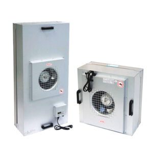
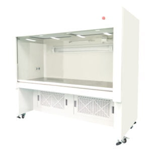
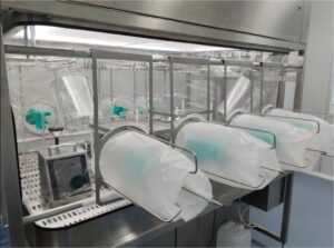
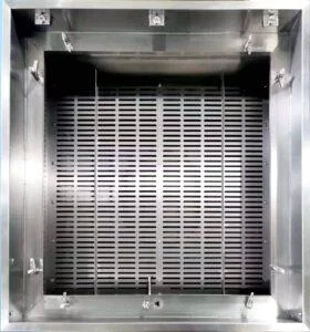
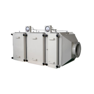
An FFU is a ceiling-mounted filtered-air unit, which means its primary interface question is how it receives and moves air across the ceiling plane it occupies. An LAF unit creates localized unidirectional clean-air protection, and because that protection can be delivered through different orientations, fan arrangements, and mounting formats, its interfaces depend on which arrangement is selected for the protected area rather than on a single standard configuration. A HEPA housing box is a terminal filter housing installed in a ceiling or wall, which places its primary interface question upstream: what air source feeds it, and how does the housing seal and integrate into that ceiling or wall opening.
These distinctions matter before any duct, power, or access item gets listed, because each family answers a different design question. An FFU’s air path is largely self-contained at the unit; an LAF unit’s air path is defined by the zone it protects and the orientation chosen for that protection; a HEPA housing box has no independent air path at all — it depends entirely on whatever upstream air system feeds it. Carrying one family’s interface logic into another produces a coordination gap. If a project team assumes a HEPA housing box behaves like a self-contained FFU, the upstream ductwork and fan source that the housing actually depends on can be left unconfirmed. If an LAF unit’s mounting format is assumed to match a standard FFU ceiling grid, the support and orientation requirements specific to that LAF arrangement may not get captured in the coordinated layout.
The practical implication is that the RFQ should state, for each location in the package, which of the three roles is intended and what upstream air source that location relies on. A location calling for room-level filtered-air delivery through the ceiling is a different design problem than a location calling for localized protection of a work zone, which is again different from a location where an existing or planned air system needs a terminal filter point. Once that role is fixed per location, the duct, power, control, and access questions that follow apply to the correct family instead of being borrowed from whichever equipment the reader is most familiar with. For a project comparing configurations, the Fan Filter Unit and Laminar Air Flow Unit families, along with the HEPA Housing Box line, represent separate starting points for this location-by-location assignment, not three options for the same slot.
| Equipment family | Supported planning role | First boundary to confirm |
|---|---|---|
| FFU | Ceiling-mounted filtered-air delivery | Air path, ceiling integration, power, control, and service arrangement |
| LAF unit | Localized clean-air protection | Protected area, orientation, support, fan arrangement, and project connections |
| HEPA housing box | Terminal filter housing in a ceiling or wall | Upstream air source, filter fit, sealing, installation, and access |
Confirm Duct, Ceiling, and Support Boundaries
Once the role at each location is fixed, the physical interface question becomes whether the unit is recirculating within the room, connected to an upstream air system, or otherwise configured for the specific project. This distinction changes almost everything downstream. A recirculating unit’s air-path coordination stays local to its own footprint and ceiling opening; a unit connected to an upstream system requires the project team to trace connection geometry back to that source, including how much of the transition ductwork falls inside the supplier’s scope versus the project’s mechanical scope. Camfil’s FFU documentation names a ceiling-system installation option as one configuration path, which illustrates that FFUs are not always freestanding, self-contained ceiling units — the installation format itself is a variable to confirm rather than assume.
Ceiling and wall openings carry their own coordination logic. The opening size, the frame condition, and the sealing method all depend on which unit occupies that location and how it was configured for the project. Terra Universal’s installation manual for its own FFU identifies grid alignment, structural support, obstruction clearance, inlet clearance, and power connection as items to confirm during installation planning — not as fixed values, but as categories of information that any comparable installation needs to resolve for its own equipment and site conditions. Where the ceiling grid is standardized and lightweight, support may come primarily from the grid itself; where heavier units or different mounting formats are involved, additional structural support points may need to be identified before the ceiling design is finalized. That difference is a project-specific structural question, not a property of the equipment family alone.
Obstruction clearance follows the same logic. Ducts, pipes, lighting, structural members, and adjacent equipment can all compete for the same ceiling void that an FFU, LAF unit, or HEPA housing box needs for its air path and its physical footprint. Where the surrounding ceiling is congested, the achievable air-path envelope may be narrower than the equipment’s nominal footprint suggests, which changes how much clearance the layout needs to reserve around each unit. Confirming connection geometry, opening dimensions, support data, and clearance requirements before the ceiling layout is fixed avoids a mismatch between what the equipment needs and what the coordinated drawing shows.
| Interface | Project input | Supplier confirmation |
|---|---|---|
| Air connection | Intended upstream air path and available space | Connection arrangement and transition scope for the selected unit |
| Ceiling or wall opening | Coordinated location and construction | Required opening, frame, sealing, and installation interface |
| Support | Project structural conditions | Equipment support points and information required for coordination |
| Obstructions | Ducts, pipes, lights, structure, and adjacent equipment | Minimum access and air-path envelope for the selected configuration |
Define Power and Control Architecture by Equipment Location
Power and control questions divide along the same line as the physical interfaces: what supply and adjustment does each unit need on its own, and what does the project want to do with multiple units together. Camfil documents handheld or BUS control with named protocols for one of its FFU families, and Price Industries documents local or BACnet control for its own equipment — both illustrate that clean-air equipment can be operated at the unit level or integrated into a broader control scheme, but which option applies to a given selection is a configuration decision, not a default.
Local operation matters where a unit’s performance needs to be checked or adjusted at the point of use, independent of any central system. Grouped or networked operation matters where a project wants to command multiple units together, monitor them from a central point, or fold them into an existing building or facility control system. These are not mutually exclusive, but the choice changes what has to be specified: a local-only unit needs a defined supply and a way to adjust and read it at the unit; a networked unit additionally needs a defined protocol, a gateway or integration point compatible with the receiving system, and a point list describing what data or control the network exchanges.
Where the project scope changes — for example where a facility later wants to add units to the same control scheme, or where a validation team wants monitoring records drawn from the control system rather than manual logs — the control architecture decided at quotation stage determines whether that later requirement is straightforward or requires rework. This is where the project information the buyer supplies becomes part of what YOUTH’s configuration and quotation review actually works from: without a stated intention for local versus grouped or networked operation, a control architecture cannot be matched to the equipment selection, because the same physical unit can typically support more than one control approach depending on what is ordered and configured.
Commissioning handoff is the point where this architecture becomes concrete. The buyer needs to know what demonstrations and records are expected at handover — whether that means confirming local indication functions correctly, confirming a network point reports correctly, or both. The supplier’s side of that handoff is configuration data and the scope of control components actually supplied, which should be confirmed against the project’s control architecture before commissioning begins rather than discovered during it.
| Decision area | Buyer should provide | Supplier should confirm |
|---|---|---|
| Power | Available supply and connection point | Required supply and supplied connection components |
| Local operation | Who needs access at the unit or room | Available local adjustment and indication |
| Grouped or central operation | Desired zones, commands, and project control system | Available grouping, protocol, gateway, and point list |
| Commissioning handoff | Required demonstrations and records | Configuration data and supplier scope for the selected controls |
Protect Filter, Fan, Control, and Test Access
Service access is the interface question most likely to be settled by default rather than by decision, because a ceiling layout can be completed without anyone confirming which side of each unit is meant to be opened. Price Industries’ documentation shows that control access may be arranged top-side or room-side depending on configuration, and that filter status and pressure-drop information can be exposed on some configurations for room-side or remote reading. Terra Universal’s manual distinguishes room-side filter replacement from ceiling-side installation constraints for its own FFUs, showing that the side used to install a unit is not necessarily the side used to service it afterward.
This distinction changes how the surrounding ceiling and room layout needs to be coordinated. Where filter replacement is intended from the room side, the room-side clearance in front of the unit needs to stay free of racking, fixed equipment, or other obstructions that would block that removal path — a constraint that has nothing to do with the ceiling void above the unit. Where service instead requires access from above the ceiling, the plenum or ceiling void needs its own clear path, and the room-side finish can be treated independently. A project that assumes one access side without confirming it risks designing a room layout that satisfies the wrong side, leaving the intended service path obstructed by equipment, storage, or fixed millwork installed after the ceiling is finished.
The same logic applies separately to fans, motors, controls, disconnecting means, and any sensors or test ports the project’s verification program requires. Each of these may have its own service side, and they do not necessarily share the same side as the filter. A control panel accessible from the room side does not guarantee that the fan or motor behind it is serviceable from the same side; a pressure-drop reading point exposed for room-side monitoring does not by itself confirm that the filter behind that reading is also replaced from the room side. Where a project’s validation or maintenance program requires access to specific test points, that requirement needs to be checked against the actual configuration rather than assumed from the general equipment family.
The coordination evidence the project team needs is a layout that shows each of these access paths as clear space, not just as a footprint. This is also where YOUTH’s equipment interfaces connect to the buyer’s next practical decision: confirming, for the selected FFU, LAF unit, or HEPA housing box configuration, which side services which component, and requesting that this be reflected in the coordinated drawing before ceiling grids, ductwork, and adjacent fixed equipment are finalized around it.
| Item to reach | Access question | Coordination evidence |
|---|---|---|
| Filter | From which side is removal intended? | Removal path shown clear on the coordinated layout |
| Fan or motor | What component must be reached or removed? | Service zone and lifting or removal boundary confirmed |
| Controls and disconnecting means | Where will adjustment and isolation occur? | Selected access side and electrical boundary recorded |
| Sensors or test points | Which project checks require access? | Required ports, points, and approach space confirmed for the selected configuration |
Frequently Asked Questions
Q: Can I use one identical interface checklist for FFUs, LAF units, and terminal HEPA housings?
A: Use a shared project schedule, but define the device-specific interfaces at each location. The intended zone, upstream air source, fan arrangement, orientation, and installation format determine which duct, power, control, and access questions apply. A terminal housing should not inherit every powered-unit requirement automatically.
Q: What does an offer described as “network-ready” need to specify?
A: It needs to specify the offered protocol, grouping, gateway if required, points, and configuration scope. Match those details to your central command, monitoring, and alarm expectations. Market examples of networked controls do not confirm compatibility for a particular YOUTH configuration.
Q: Can I leave duct transitions and support details for the installer to resolve later?
A: Those boundaries should be clarified before quotation comparison. Provide the intended air path, available space, opening construction, and structural conditions, then ask which connection, transition, frame, and support items the supplier includes. Undefined boundaries can make apparently similar offers cover different work.
Q: Is a clear filter replacement route enough to approve service access?
A: No. Fans, controls, sensors, disconnecting means, and test points may require different approach or removal space. Have the proposal and coordinated layout show each applicable access side and envelope, including conflicts with ducts, pipes, lights, structure, or adjacent equipment.