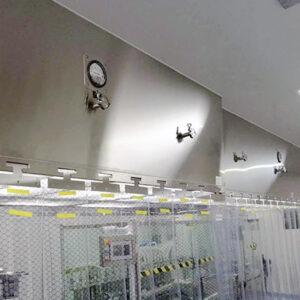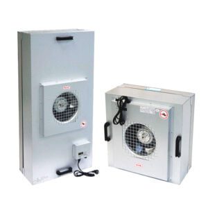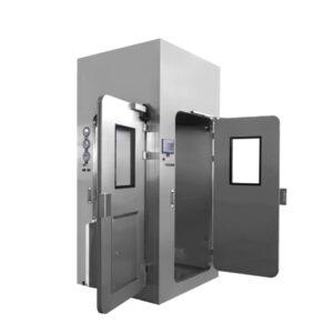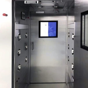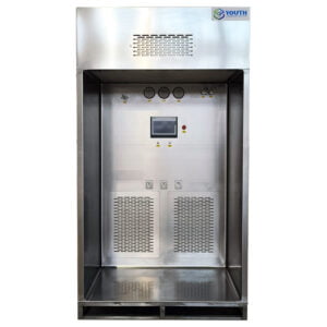
A nominal FFU size tells a buyer which product family and ceiling module a unit is designed around, but it does not confirm that the physical unit will pass through the ceiling opening, seat correctly on the grid, or leave room for the service access the project needs. When the purchase decision is made from the nominal label alone, the risk moves downstream to installation, where a dimensional conflict is far harder to resolve than it would have been on paper.
Distinguish Nominal Module Size From Actual Unit Envelope
A nominal module size describes a family of units built to fit a common class of ceiling grid, not the exact dimensions of the unit a buyer will receive. Lawrence Berkeley National Laboratory’s best-practice report on fan-filter units notes that FFUs are modular fan, filter, and controller assemblies commonly built to fit standard cleanroom ceiling grids, and it gives typical module examples for illustration. That framing is useful for understanding why FFUs are described by grid-related sizes at all, but a typical example from an industry report is not evidence of what a specific supplier’s unit measures, and it must not be treated as a YOUTH dimension or as proof that any given grid will accept any given unit.
The distinction that matters at purchase time is between the nominal module, the clear ceiling opening, and the actual unit envelope. The nominal module is a naming convention tied to a family of ceiling grid spacings. The clear opening is the physical gap available in the coordinated ceiling once framing, trim, and adjacent components are accounted for. The actual unit envelope is the supplier-stated width, length, and depth of the specific unit, including any component that protrudes beyond the main body, such as a housing lip, control enclosure, or inlet fitting. Where these three figures are treated as interchangeable, a unit that carries the correct nominal label can still fail to pass through the opening or can leave no clearance once it is seated.
The Price Industries fan-filter-unit installation manual illustrates this separation from the installer’s side: it shows a specific unit being raised through a grid opening and lowered onto the supporting tees, which demonstrates that insertion and seating are physical, unit-specific events, not properties that follow automatically from a nominal size match. That illustration describes Price’s own documented models and cannot be read as a description of how a YOUTH unit is installed; it is useful only for identifying which interface categories — opening, envelope, protrusions, seating — need confirming before an order is placed. Where a project ceiling has already been built or is close to final coordination, the clear opening becomes a fixed constraint that any candidate unit’s envelope must satisfy, rather than a figure that can move to accommodate the equipment.
| Dimension or interface | What it describes | Purchase use |
|---|---|---|
| Nominal module size | Product-family or ceiling-module designation | Initial shortlist only |
| Clear ceiling opening | Available opening in the coordinated ceiling | Check insertion and interference risk |
| Actual unit envelope | Supplier-stated width, length, depth, and protrusions | Confirm physical fit |
| Support and seating detail | Load path, bearing or suspension points, and seal location | Confirm structural and interface coordination |
| Service envelope | Space and direction needed to reach filters, fan, and controls | Confirm maintainability before release |
Match the Unit to the Ceiling Grid and Support Detail
Once the envelope is confirmed against the opening, the next judgment is how the unit is carried by the ceiling structure. Ceiling-mounted equipment of this kind is generally supported in one of a small number of ways: it can bear directly on the grid tees, it can be suspended or supported independently of the grid so the grid carries only its own finish load, or it can use another detail specific to the ceiling system in use. Which of these applies changes what the buyer needs to confirm before purchase, because a unit intended for grid bearing will have different weight-transfer and leveling requirements than one designed for independent support.
The Price manual illustrates grid seating, overhead support, leveling, and gasket compression sequences for its own documented models. That sequence is useful for understanding the category of details a support arrangement must address — how the unit is seated, how it is leveled, and where the sealing surface sits relative to the ceiling finish — but the manual describes Price’s models only, and it cannot be used to infer how a YOUTH unit rests on a grid or is otherwise supported. The project designer and YOUTH need to confirm the actual support detail for the specific ceiling system and unit combination in the project.
The gasket or seal interface deserves separate attention because it sits at the boundary between structural support and the room’s containment performance. Where a unit is designed to compress a gasket against the ceiling grid or an opening frame, the seating detail and the leveling tolerance both affect whether that compression is achieved evenly. A support detail that is dimensionally compatible but does not achieve the intended seal compression creates a containment problem that a purely dimensional check will not catch, so seal location needs to be confirmed as part of the same review, not as an afterthought once fit is settled. Where the ceiling system itself is still being selected, the wall and ceiling system for the project and the FFU support detail need to be coordinated together rather than treated as sequential, independent purchases, because the grid type and finish detail determine what support and seal options are physically available.
Check Filter, Seal, and Maintenance Access
Fitting the unit into the ceiling is a necessary condition for purchase, but it is not sufficient, because the unit also has to be serviceable once it is installed. Filters, fans, motors, and controls need a defined access route and enough clearance for the specific removal action that route requires, and that access can come from the room side, the plenum side, or both, depending on the unit’s design and how it has been installed.
Where access is from the room side, the maintenance team needs clear space below the unit and possibly the ability to work at ceiling height without disturbing adjacent equipment. Where access is from the plenum side, the constraint shifts to whatever clearance exists above the ceiling, which is often less visible during a walkthrough and easier to overlook during specification. A project that has coordinated the visible ceiling opening carefully can still have an access conflict above the ceiling that only becomes apparent when a technician attempts a filter change and cannot reach the removal point without disturbing adjacent panels or ductwork.
The seal interface reappears here as a maintenance question, not only a structural one: the terminal seal or filter-fit boundary determines where contamination control is established, and any maintenance action that disturbs that boundary needs a defined method for restoring it. This is a category of interface to confirm, not an instruction — the point is that the buyer should ask which components can be reached without removing adjacent work, whether the manufacturer’s access direction matches what the installed ceiling actually allows, and what clearance the service action requires. None of this should be inferred from a general expectation about how FFUs work; it needs to be confirmed against the specific supplier’s submittal, because access direction and removal envelope are unit-specific design choices, not properties that follow from the nominal size or grid compatibility already checked.
Inlet components, where a unit includes a prefilter, collar, or other accessory ahead of the main filter, add a further access and clearance question, since these components occupy plenum or duct space that the physical fit review may not have accounted for if it stopped at the visible ceiling envelope.
| Check | Project-side information | Supplier submittal information | Decision |
|---|---|---|---|
| Filter access | Available room-side or plenum-side route | Filter access direction and removal envelope | Confirm access without assuming adjacent work can be removed |
| Fan and control access | Available service space and restrictions | Component access direction and clearance | Confirm maintainability |
| Ceiling seal | Grid, opening, and finish detail | Gasket or seal interface | Confirm coordinated closure |
| Inlet components | Plenum or duct space and obstructions | Inlet, collar, prefilter, or accessory envelope when applicable | Confirm no physical conflict |
Confirm Airflow and Service Interfaces After Physical Fit
A unit that fits the opening, seats correctly on its support, and offers workable access can still be the wrong selection if its airflow and service interfaces do not match the system it is entering. Physical fit and functional fit are separate release gates, and treating a passed dimensional check as evidence of overall compatibility skips a step that has its own failure modes.
Airflow direction is the first of these interfaces. An FFU delivers air in a defined direction relative to its housing, and the room’s design assumes that direction relative to the workspace, return path, and adjacent equipment. A unit that is dimensionally correct but oriented, or configured, for a different airflow arrangement than the room requires will not deliver the intended air pattern even though it occupies the opening correctly. The inlet arrangement is a related interface: where the unit draws air from a plenum, duct, or open ceiling void, the upstream path needs to be free of obstruction and matched to what the unit’s inlet is designed to accept.
Power and controls form a second interface category. The unit’s control approach, whether integrated or connected to a separate control point, needs a defined electrical and signal path that has to be coordinated with the ceiling and plenum layout established during the physical fit review, since conduit or cable routing can itself become a clearance conflict if it is not planned alongside the mechanical support detail.
Test ports or other provisions for site measurement are a third category worth confirming early rather than late, because where a project intends to verify airflow performance after installation, the access needed for that measurement has to be designed in from the start; retrofitting a measurement point into a sealed or inaccessible installation is a different problem than confirming one exists before the unit is ordered. Where the project’s measurement plan calls for a specific test approach, the unit and its installed position both need to support that approach, which is a functional question distinct from whether the unit physically fits the ceiling.
Release the Purchase Only Against Approved Dimensional Data
The purpose of everything reviewed to this point is to establish what the controlling record for purchase should be. A nominal size is a starting point for a shortlist; it is not documentation that can be released for fabrication or ordering. The record that should govern the purchase is the coordinated project opening and support detail matched against the supplier’s exact submittal for the specific unit under consideration, because that is the only record where the ceiling condition and the unit’s actual dimensions have been checked against each other rather than assumed to align.
This distinction matters most when a project is under schedule pressure to place an order before every drawing is finalized. Where the ceiling design and the equipment submittal are both still in draft, proceeding on a nominal size match carries the risk that later revisions to either the ceiling opening or the unit’s envelope will surface only after the order is committed. Where both the ceiling drawing and the supplier submittal have reached an approved, coordinated state, the purchase record can reference exact figures rather than provisional ones, and that is the condition under which release is appropriate.
Because ceiling and equipment drawings can go through multiple revisions before reaching that coordinated state, the purchase record should capture which revision was used for approval, along with any approved exceptions to the standard interface, the confirmed access direction, and any interface that remains open at the time of order. An open interface is not necessarily a reason to delay every purchase decision, but it is a reason to record explicitly what remains unresolved so that the gap is tracked rather than lost once the order proceeds. When a project team submits its coordinated opening, support detail, and access requirements for a configuration or quotation review, that submitted information is what allows the review to confirm fit against the actual unit rather than against a nominal label. A catalogue label describing a product family is a reasonable way to begin comparing options; it is not the same record as the approved dimensional data that should authorize fabrication or shipment.
Frequently Asked Questions
Q: Our ceiling and the FFU have the same nominal module size. Is that enough to order?
A: No. Match the clear opening to the actual unit width, length, depth, and protrusions, then confirm support, seating, and seal details. The nominal label is useful for shortlisting; the coordinated opening and exact supplier submittal should control purchase release.
Q: If an FFU can pass through the opening, does that confirm the ceiling can support it?
A: No. The insertion route and load path are separate questions. Ask how the offered unit is supported and reconcile its support points with the project detail. Do not assume grid bearing or independent suspension from a dimensional match.
Q: What dimensions should I request when overhead ducts limit available space?
A: Request the complete unit and accessory envelope, including depth and any inlet, collar, prefilter, or other protrusion offered. Also request fan and control service clearances and the filter removal direction. Compare both installation and service envelopes with the coordinated overhead layout.
Q: What should the purchase record identify after dimensional approval?
A: Identify the exact supplier submittal revision, matching project opening and support detail, approved exceptions, and access direction. Keep airflow, power, controls, upstream air path, and test interfaces visible as separate confirmations. Dimensional approval alone does not resolve those system requirements.