A filter bank pressure drop figure is only usable for fan selection when it is tied to three stated things: the airflow through the bank, the filter configuration that produces that resistance, and whether the value describes clean filters or the loaded condition at which the filters will be changed. A resistance number without those qualifiers cannot be checked against a fan curve, because filter resistance rises roughly with flow and rises again as the media loads. Before any fan is sized, confirm that the quoted allowance covers every stage the air passes through, not only the filter the conversation happens to be about.
Define the airflow and clean-to-changeout pressure basis
The basis for fan selection is a stated airflow, a stated filter configuration, and a stated resistance condition — clean, or the intended changeout condition. All three travel together. A medium filter rated at a given resistance passes that resistance only at the airflow on its curve, and if the bank is run above or below that point the actual value moves with it.
The clean-to-changeout distinction decides whether the system can hold its design airflow for the whole life of the filters. A fan sized against clean-filter resistance alone meets the design flow on the day of commissioning and then drifts downward as dust accumulates, which in a cleanroom shows up first as fewer air changes and a weakening pressure cascade before it shows up as a filter alarm. A fan sized against an agreed changeout condition carries the spare pressure to hold flow across that range. Decide early which condition the project will treat as the design duty, and say so in writing, because the same filter model supports both numbers and the supplier cannot guess which one you intend.
Filter configuration belongs in the same statement. Element depth and media area change resistance at a given airflow: a deeper V-bank or box-style medium filter presents more media area than a shallow panel of the same face size and therefore lower resistance at the same flow. When you ask for a resistance figure, name the face size, element depth or format, filtration class and the number of elements in the bank, or the figure describes a filter you are not buying.
Account for parallel elements and assembled bank losses
Elements mounted side by side in a bank share the airflow; they do not each see the full bank airflow. The resistance of the bank is interpreted from the flow through one element, read against that element’s pressure curve — not from adding the individual drops together as though air passed through each one in turn. Adding them in series overstates the bank badly and pushes fan selection toward a machine that will run throttled or off its efficient range.
The working figure is therefore flow per element: divide the bank airflow by the number of installed elements, read the element curve at that value, and treat the result as the resistance of the filter stage. This also explains why element count is a design variable rather than a detail. Adding elements to the same bank lowers the flow each one handles, which lowers both the pressure drop and the face velocity, and usually extends the interval before the loaded condition is reached — at the cost of a larger plenum and more filters to stock and change.
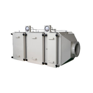
An element curve describes the filter, not the assembly around it. Holding frames, blank-off panels, header seals, duct transitions into and out of the plenum, and any turning or contraction upstream of the filter face all add resistance that no filter datasheet includes. Uneven approach velocity makes this worse, because a transition that loads one part of the bank face harder than the rest raises the assembled drop above the clean sum of its parts. Ask whether the quoted figure is for the bare element or for the assembled bank with its frame system, and if the answer is the element, ask the person responsible for the housing design what the assembly adds.
Build the complete air-path pressure budget
The fan has to overcome everything in the air path, so the pressure budget must list every resistance in series at the design airflow, not just the filter stage under discussion. In a typical cleanroom supply arrangement that includes the prefilter, the medium filter, the final HEPA stage, cooling and heating coils, humidification sections, attenuators, dampers, the supply and return ductwork with its fittings, any terminal housing or fan filter unit, and the return or exhaust path back to the air handler. Each of these is sized at the same airflow and their resistances add, because the air passes through all of them in turn.
Checking one filter in isolation is how shortfalls hide. A medium filter that looks comfortable on its own can still leave the system short if the HEPA stage, a dirty prefilter and a long duct run are consuming pressure that was never written down. The same applies in reverse: if the terminal HEPA housings carry most of the final resistance, improving the medium filter changes less than the specification implies.
Two entries in the budget need an explicit condition attached. Filters are the obvious one — enter each filter stage at its agreed clean or loaded value, consistently across stages, and state which. The other is the terminal stage: a terminal HEPA housing adds its resistance to the central fan’s duty, while a fan filter unit carries its own fan and its own filter, so its resistance sits with that unit rather than with the air handler, though the air handler still has to deliver conditioned air to the unit’s inlet at the required static pressure. Getting that boundary wrong either double-counts the HEPA or leaves it out entirely. ISO 14644-4:2022 treats cleanroom design, construction and start-up as a connected project process, which is a useful reminder that the air path, not the individual component, is what gets built and verified.
A worked illustration, with assumed values left to the project: take the design supply airflow, divide it across the installed elements in each filter bank to get the flow per element, read each stage’s resistance from its own curve at that flow, add the assembled bank losses for frames and transitions, add the coil, duct, damper and terminal resistances at the same airflow, and then add the agreed filter loading allowance. That total, at that airflow, is the fan duty to quote against.
Compare bids and check the fan control range
| Comparison or check | Evidence to compare | Decision it supports |
|---|---|---|
| Quoted initial filter pressure drop | Resistance quoted at the same airflow, element size and installed element count | Whether the bids provide a comparable basis for ranking initial resistance |
| Fan control range | Proposed control range against the required airflow across the intended filter operating range | Whether the proposed control response addresses increasing filter resistance |
| Available fan pressure | Available fan pressure against the agreed loaded-filter duty | Whether the selection addresses the intended loaded-filter duty rather than only a clean-filter allowance |
| Fan operating limits | Operating limits against the agreed loaded-filter duty | Whether the intended duty falls within the proposed fan operating limits |
Two filter bids are comparable only when they are normalized to the same airflow, the same element size and the same number of installed elements; until then, the lower quoted initial pressure drop may simply describe a filter working harder or a bank with more elements in it. A quote based on a larger element count carries less flow per element and therefore shows a lower resistance, which looks like a better filter and is actually a different bank. Rebuild both offers on the specified configuration before ranking them, and if a bidder proposes a different element count or depth, treat that as a change to the bank design with its own plenum, cost and changeout implications rather than as a cheaper filter.
The second half of the comparison is the fan itself, and it is a different question from capacity. A nominal fan rating states what the machine can move; it does not state how the system will hold its design airflow while filter resistance climbs toward the changeout condition. What answers that is the proposed control arrangement — variable speed, flow or pressure control, and the control band it operates within — together with the available fan pressure and the operating limits at the agreed loaded-filter duty.
Three things make that check concrete. Ask for the fan curve with the system resistance line drawn on it at both the clean and the loaded filter condition, so the operating points at each end of the filter life are visible. Ask where those two points sit relative to the fan’s stable operating region and its speed, power and temperature limits. And ask how the control loop maintains the required airflow between them — whether it responds to measured flow, to a duct pressure setpoint, or to a fixed speed schedule — because a fixed-speed arrangement that is correct when clean will drift as the bank loads. A selection that answers only the clean point has left the loaded duty unanswered, and the loaded duty is the one the room has to live with.
Keep the resistance comparison and the filter’s other properties separate. Filtration class, media type, moisture tolerance, frame material and expected service life all bear on the choice and none of them are visible in a pressure figure, so a bid that wins on initial resistance alone has only won one of several comparisons.
Record a usable commissioning baseline
A commissioning baseline for a filter bank is a short, specific record: the measured bank airflow at the time of the reading, the physical location of the pressure taps on each side of the bank, the identity of the installed filters — manufacturer, model, class, size and element count — and the differential pressure readings for individual stages wherever separate taps exist. Date each set of readings and note the fan speed or control setpoint in force when they were taken.
Each item exists because of a specific ambiguity it removes later. Without the airflow, a higher differential pressure a year on could mean loaded filters or simply more flow, since resistance rises with flow on the same filters. Without the tap locations, a later reading may span a different part of the air path — across the element only, across the frame and element, or across the whole plenum — and the two numbers are not comparable. Without the filter identity, a replacement element of a different depth or media can shift the baseline on its own. And without stage-by-stage readings, a rise across a multi-stage bank tells you the bank is restricting without telling you which stage is doing it, which is the difference between changing a prefilter and investigating a HEPA.
Stage readings are also what make the investigation path sensible when the room later runs low on air. Compare the current reading against the baseline at the same airflow and the same taps; a change isolated to the prefilter points to normal loading, a change at the final stage points to the HEPA or to a seal or bypass condition, and a flat differential with falling airflow points away from the filters altogether and toward the fan, drive or control. ISO 14644-3:2019 describes test methods for installed cleanroom performance parameters, and a baseline that records the same measurement boundaries each time is what lets successive results be read against one another.
Whether a loaded bank is changed, left in service or returned to service after work is a decision governed by the project’s approved procedure and its designated approver, informed by the baseline rather than settled by it. For the supplier discussion that precedes all of this, have the design airflow and element count for each bank, the filter classes and formats intended at each stage, a list of the other resistances in the air path at that airflow, the agreed changeout condition, and the room’s pressure and air-change requirements, so the resistance figures you receive describe the bank you are actually building.
Frequently Asked Questions
Q: What should I include in a fan enquiry if the final filter configuration is still undecided?
A: Keep the candidate configurations explicit instead of supplying one unqualified pressure-drop allowance. For each option, state the required airflow, element size and count, and the clean and intended changeout resistance basis. Include the remaining air-path losses so the fan comparison addresses the complete duty.
Q: Can I reduce the fan pressure allowance by installing more filters in parallel?
A: Do not assume a reduction from element count alone. Check each element’s pressure curve at its share of the bank airflow, then account for the assembled frames and transitions. Any revised bank allowance must still sit within the pressure budget for the other filter stages and air-path components.
Q: Can we retain an existing fan when changing the filter specification?
A: Treat retention as a duty check rather than a like-for-like replacement assumption. Compare the proposed filters at the required airflow, including their intended loaded condition, then check the existing fan’s available pressure, control range and operating limits against the complete air path. A clean-filter comparison alone does not establish suitability over the intended operating range.
Q: Does a higher bank pressure reading mean the filters have reached their changeout condition?
A: A higher reading alone does not establish that conclusion. First compare airflow, pressure-tap locations and filter identity with the commissioning baseline; use individual stage readings where available to clarify the measurement. Assess the comparable result against the agreed changeout condition before making the decision.