A mixed air-delivery system rarely fails because someone chose the wrong controller. It fails because no one defined, before specification, which fan filter units needed to move together, who needed to reach them, and what the project meant by “control” in the first place. Settling local versus central control is really a series of smaller decisions about zones, signals, and access — and getting those sequenced correctly changes what a supplier can actually configure.
Start With Operating Zones, Not the Controller Label
“Local” and “central” describe where a command originates, not what the system is supposed to do. Before a buyer can compare control paths, the project needs to define its operating zones: the groups of FFUs that must respond together, the groups that must remain independent, and the boundary conditions that separate one zone from the next. A zone is not necessarily a room. It can be a process area within a room, a set of units serving one workstation, or a single independent unit that has no operational relationship to its neighbors.
This matters because control architecture follows zone logic, not equipment count. Where a project has many FFUs but only a few independent operating groups, a networked system may be doing far more work than the zoning requires. Where a project has fewer units but each one needs distinct scheduling, access, or condition-based adjustment, even a small deployment can justify something more structured than simple local adjustment. The number of zones is a project input the buyer defines from the room and process arrangement, not an assumption carried over from a similar-looking installation.
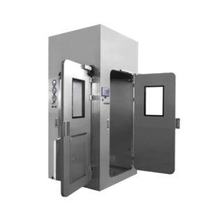
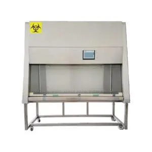
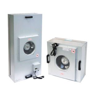
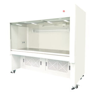
Zone definition also has to separate air delivery from control responsibility. A fan filter unit and a laminar air flow unit may both move filtered air into a work zone, but they do not necessarily share a control scheme, and a terminal filter housing without its own fan has no control question at all in the same sense — its role is passive air delivery, not commanded operation. Grouping these together under one control conversation, simply because they sit in the same room, obscures which equipment actually needs a command path and which only needs airflow verification.
Access requirements belong in this same zoning exercise. Who needs to change a setting, and under what condition — schedule change, process change, maintenance activity — determines whether a zone can be managed at the unit or needs a shared point of access. Manufacturer documentation illustrates this range at the product level: Camfil’s CamFFU HP-EC family lists handheld or BUS control options for a single FFU line, while Price Industries’ PURAFLO catalog documents local or BACnet control for its own clean-air equipment. Both show that control location is a configurable product attribute, not a fixed feature of “an FFU” in general — which is exactly why the buyer’s zone definition, not the equipment category, has to come first.
Compare Local, Grouped, and Networked Control Paths
Once zones are defined, the three broad control paths become comparable on their own terms rather than as competing generic options. Local control places the command and indication at the equipment itself. It removes any dependency on a communication network, which simplifies both installation and troubleshooting where a zone genuinely stands alone. Its cost is distributed access: anyone who needs to check status or make an adjustment has to be physically at the unit, and coordinating multiple units under local control requires separate action at each one.
Grouped control sits between the two. It aligns several FFUs that serve one room or process zone under a shared point of command, without necessarily extending that command into a plant-wide network. This fits situations where a zone has more than one unit but the project has no requirement to expose that zone’s status beyond its own boundary. The trade-off is that grouped control introduces a panel, wiring, and a defined membership list — decisions that have to be revisited if the zone’s boundary changes later.
Networked or central control extends commands, status, and often trendable data points into a broader project control system. Camfil’s documented options for its HP-EC family include LON, Modbus, or 0-10 V control, and Price’s catalog distinguishes local operation from BACnet-based operation with monitored points such as filter status and pressure drop. These examples establish that protocol availability is product-specific and varies by manufacturer and configuration — a fact the buyer has to treat as a question for YOUTH’s own equipment rather than an assumption drawn from another supplier’s catalog.
The decision frame is not that networked control is more capable in an unqualified sense. It is that networked control matches a project need for remote visibility, coordinated alarms, or centralized trending, and that need has to exist before the added complexity — gateway configuration, addressing, cybersecurity boundary, integration ownership — is worth carrying into the project. Where a zone has no requirement to report outward, local or grouped control avoids that overhead. Where the project’s controls team already manages a building or facility network and expects the FFUs to report into it, networked control becomes the frame that actually serves the project, provided the protocol and point availability are confirmed for the selected configuration.
| Control path | Fits the decision when | Boundary to confirm |
|---|---|---|
| Local adjustment | A unit or small independent group can be managed at its location | Safe access, allowed settings, indication, and responsibility |
| Grouped control | Several FFUs need coordinated commands within a defined zone | Zone membership, panel capacity, wiring, and local override |
| Networked or central control | The project needs remote commands, status, alarms, or trendable points | Protocol, gateway, point list, cybersecurity boundary, and integration responsibility |
Define Signals, Power, Access, and Failure Boundaries
Choosing a control path only sets the frame. The buyer still has to define the interfaces inside that frame: how power reaches each unit, what signals travel where, who can reach a unit physically, and what happens when a link or a unit is unavailable.
Power distribution is a project input before it is a control question. The available supply concept — how power reaches the units and panels, and where isolation occurs — shapes what control functions are even possible at that location. A unit wired for simple on/off power cannot expose speed or mode commands without a different distribution and wiring approach, regardless of which control path was chosen conceptually.
Commands and feedback have to be listed, not assumed. A project may want on/off, speed adjustment, mode selection, or schedule-based operation as commands, and status, alarm, or monitored values as feedback. Price’s PURAFLO documentation shows that specific equipment can expose points such as filter status and pressure drop alongside local or BACnet control access — but that list applies to the cited Price products, not to any FFU as a category. The buyer’s own point list has to be confirmed against what the selected configuration actually makes available, since a desired point that does not exist on the chosen unit cannot be recovered later without a hardware change.
Network topology, where a networked or grouped path is chosen, needs its own confirmation: which protocol the project platform expects, whether a gateway is required, how addressing is managed, and who owns that configuration once installed. This is where the boundary between equipment supplier and project controls integrator has to be explicit, because a control point that exists on the unit is not the same as a point that has been mapped, addressed, and verified in the project system.
Access and fallback close the set. Operator and service access constraints determine whether local override is needed even inside a grouped or networked scheme — a unit that can only be commanded remotely may still need a documented local access path for service conditions. Terra’s equipment manual illustrates that FFU power and physical access are installation interfaces at the unit level, which is a separate concern from the communication interface layered on top. The response to a communication loss or an isolated unit — what the system does, and what a technician is expected to do — is not something the buyer should assume or specify unilaterally. It has to be documented by the supplier and the project controls team together, because an unverified fail-safe assumption carried into commissioning becomes a gap discovered under test rather than resolved in design.
| Interface | Project input | Confirmation required |
|---|---|---|
| Power distribution | Available supply and distribution concept | Unit, panel, connection, and isolation requirements |
| Commands | Required on/off, speed, mode, or schedule functions | Functions actually available for the selected configuration |
| Feedback | Desired status, alarm, and monitored values | Available signals, scaling, and destination |
| Network | Project control platform and preferred protocol | Compatibility, gateway, addressing, and configuration scope |
| Access and fallback | Operator and service access constraints | Local access and documented response when a link or unit is unavailable |
Turn the Choice Into a Testable Project Handoff
A control architecture decision only has value once it is written down in a form that design, construction, and commissioning teams can act on and verify against. ISO 14644-4 describes how requirements carry through design, construction, start-up, verification, and ongoing maintenance consideration for cleanroom projects — it establishes that this chain of custody for information matters, without prescribing what the control architecture should be or who holds contractual responsibility for each interface. That allocation is the project’s own work.
The handoff record should state the architecture chosen — local, grouped, or networked — and the zone membership behind it, so that anyone reviewing the project later can trace which units belong to which operating boundary. It should list the commands and feedback points agreed for that architecture, distinguishing points that are available on the selected equipment from points the project system still needs to receive through mapping or configuration. It should name the party responsible for configuring those points, since a point list without an owner tends to surface as a gap during integration rather than during design review.
Drawings and point schedules belong in this record for the same reason: a control diagram showing panels, zones, devices, and communication paths gives the commissioning team something to check equipment against, but it only reflects the final selection once that selection is actually made — it cannot substitute for the equipment and interface decisions still open earlier in the project.
Commissioning evidence has to be project-specific. Selecting a protocol, or documenting that a unit supports BACnet or another communication scheme, is not evidence that the installed system performs as intended or that the room meets its required condition. Acceptance criteria and the parties responsible for verifying them are decisions the project makes, not conclusions that follow automatically from an equipment choice.
The record should also state plainly what remains outside the FFU supplier’s scope — network infrastructure beyond the unit’s interface, building-level integration, or room-side commissioning activities that depend on other trades. Where a buyer is preparing this information for review, structuring it this way gives YOUTH’s configuration and quotation review a defined starting point: a zone list, a point list, and a stated control path, rather than a request to infer those decisions from equipment names alone. From there, connecting the chosen FFU configuration, and any related laminar air flow unit or terminal housing in the same mixed system, to the project’s delivery and integration sequence becomes a matter of confirming interfaces against this record rather than renegotiating the architecture at installation. Readers preparing this handoff alongside a broader supplier review may find it useful to work from the same documentation discipline described in Youthfilter’s cleanroom equipment procurement and supplier assessment guide.
| Handoff evidence | What it should establish | Open boundary |
|---|---|---|
| Control diagram | Panels, zones, devices, and communication paths | Final equipment and interface selection |
| Point schedule | Commands, feedback, alarms, and ownership | Available points and project-system mapping |
| Configuration record | Zone membership and agreed settings | Who configures, reviews, and retains the record |
| Commissioning plan | Project-specific functional checks and participants | Acceptance criteria and responsibility must be defined by the project |
Frequently Asked Questions
Q: Is central FFU control necessary if I have only one independently operated room?
A: Not necessarily. Local adjustment may suit a small independent operating boundary if the required access, indication, and settings can be managed at the units. Remote commands, alarms, or trendable points may justify another architecture; define those needs before choosing a controller label.
Q: Can FFUs serving different processes share one control group?
A: They should share a group only if the project’s operating requirements support coordinated commands. Define which units must operate together and which conditions or schedules differ. Record zone membership and local override needs so the supplier can confirm the proposed grouping.
Q: Will specifying the same protocol as our building system establish compatibility?
A: No. The offered points, gateway, addressing, mapping, and configuration scope still need confirmation. Ask the supplier and project controls team to agree the control diagram and point schedule, including who supplies sensors, receives alarms, and completes integration.
Q: What should the quotation say about communication loss?
A: It should document the proposed response for the selected configuration and identify what remains for project confirmation. Define your required operating and service-access expectations, then ask how units and controls behave when a link or unit is unavailable. Do not infer fallback behavior from the choice of protocol.