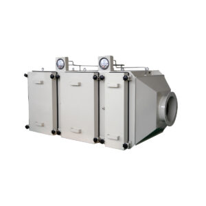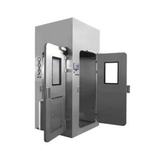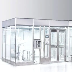
A facility replacing a loaded intake filter bank on a fixed schedule, or reacting to resistance alarms during high dust-load periods, faces a specific coordination question: does the service burden of repeated filter-bank changes justify evaluating an automatic roller arrangement instead? The answer depends on the intake duty, the service plan already in place, and how much the project is prepared to manage additional mechanical and control interfaces in exchange for continuous media advance.
What Project Conditions Make a Roller Arrangement Worth Comparing
An automatic roller pre-air filter advances a media spool across the air stream as loading accumulates, rather than relying on a technician to remove and replace a static filter bank. This changes the service model from a scheduled or alarm-triggered change-out event to a continuous or stepped advance process governed by the equipment’s own controls. Whether this difference matters to a given project depends on how the intake duty behaves over time and how the facility currently manages filter-bank service.
Where the intake air carries a steady, moderate dust load and the facility’s service plan already accommodates filter-bank changes without disrupting production or cleanroom operation, the case for comparing a roller arrangement is weaker. The conventional approach already matches the duty, and introducing a roller system adds drive, control, and spent-media handling interfaces without a corresponding service benefit. Where the intake duty produces loading events that make repeated filter-bank changes a recurring service task, or where the facility’s operating plan does not tolerate the access and downtime a filter-bank change requires at each event, a roller arrangement becomes a comparison worth making on its own terms.
This is a project-level screening question, not a default preference for one equipment type over another. The same cleanroom or process air system might be well served by a conventional filter bank in one configuration and by a roller arrangement in another, depending on how the upstream air source behaves and how the facility’s maintenance staffing and access windows are structured. A project team evaluating this question should look first at the intake condition itself: what the dust load does over an operating cycle, whether it is consistent or variable, and whether the existing service plan treats filter-bank changes as a manageable task or as a recurring constraint on continuity.
The comparison also depends on where in the air-handling path the pre-air filter sits and what it protects downstream. A pre-air filter stage protects downstream filtration equipment, including higher-efficiency room-air equipment, from the bulk of the incoming particulate load. Where the downstream stage is sensitive to upstream loading variation, the service continuity of the pre-air stage carries more weight in the overall system’s reliability, which raises the value of evaluating how each candidate’s service model holds up under the project’s actual duty.
Dust Load and Service Continuity as the Initial Fit Screen
| Project condition | Evidence that strengthens the case for comparison | Evidence that lowers its priority | Decision to make |
|---|---|---|---|
| Intake dust duty | Loading events make repeated conventional filter-bank changes a material service burden | Conventional filter-bank changes remain manageable within the service plan | Whether automatic media advance merits detailed evaluation |
| Service continuity | The service plan benefits from advancing media without a filter-bank change at each loading event | The service plan can accommodate conventional filter-bank changes | Whether the continuity benefit justifies evaluating the added roller-system interfaces |
The first screen a project team should apply is not product selection but duty characterization: does the intake dust load, combined with the service continuity the project requires, justify a detailed roller-filter comparison at all? This is a project-level gate because it determines whether the added mechanical and control interfaces of a roller system are worth evaluating in depth.
Dust loading duty is not a single figure; it is a relationship between how much particulate the intake air carries, how that loading accumulates over an operating cycle, and how the resulting resistance rise interacts with the air-handling system’s tolerance for pressure drop change. Where loading events are frequent enough that each one requires a filter-bank change to restore acceptable resistance, the service burden compounds over the system’s operating life. Where loading is light enough that a filter bank reaches its change criterion only infrequently, the conventional approach already carries a low service burden, and the roller system’s main advantage, avoiding a change event, has less to offer.
Service continuity is the second half of the screen, and it is independent of dust load. A project can have a moderate dust load but a service plan that cannot tolerate the access, isolation, or downtime a filter-bank change requires at each event, because of production scheduling, cleanroom re-entry procedures, or restricted access windows. In that case, the ability to advance media without a conventional change event at each loading event becomes the deciding factor, even where the underlying dust load would not by itself justify the equipment’s added complexity.
These two conditions interact rather than operate independently. A heavy dust load paired with a service plan that already accommodates frequent changes may not justify comparison, while a moderate dust load paired with a service plan that cannot absorb change events might justify it strongly. The project team’s task at this stage is to characterize both conditions honestly before moving to equipment-level evaluation, since the screen determines whether the remaining comparison work is worth doing.
Space, Access, Media Handling, and Maintenance Interfaces
Once a project passes the initial fit screen, the comparison shifts from whether to compare at all to what a complete roller-filter installation actually requires. An automatic roller arrangement is not a drop-in replacement for a filter-bank housing; it introduces a set of interfaces that a conventional filter bank does not have, and each one carries its own space, access, and maintenance implications.
The drive mechanism that advances the media spool requires space and a power or control connection, which changes the housing footprint and the utility coordination compared with a passive filter-bank frame. The media spool itself, both the supply side and the take-up or spent-media side, requires space for the roll and a path for spent media to be removed or handled, which is a maintenance task a filter-bank change-out does not include in the same form. Where the installation location has restricted service access, the spent-media handling step can be harder to execute cleanly than a filter-bank swap that is contained within a single housing opening.
Access for maintenance personnel is a separate consideration from access for air-handling performance. A filter-bank housing is typically designed around a single, well-defined access point for the change-out task. A roller system’s access requirements are distributed across the drive, the control interface, the media spool, and the spent-media path, which means the housing and surrounding duct or wall configuration need to accommodate multiple service points rather than one.
These interfaces do not disqualify a roller arrangement where the project’s dust-load and continuity conditions favor it; they define what the project needs to coordinate before committing to one. A project team should map each interface against the installation location’s actual space and access conditions, confirming that the drive, spool, and spent-media path can be serviced without conflicting with the room’s cleanliness or access control requirements. Where the installation sits within or adjacent to a classified space, this coordination also touches how the room’s envelope and access points are configured, since maintenance activity on the filter stage should not compromise the room’s controlled condition.
Drive, Controls, Advance Logic, and Failure Response to Define
Beyond physical interfaces, a roller arrangement introduces a control layer that a conventional filter bank does not have, and this layer needs to be defined in its own terms before a meaningful comparison is possible. The drive mechanism, the control logic that triggers media advance, and the response when the system reaches a failure or exhaustion condition are three distinct things a project team should be able to describe for any candidate under consideration.
The drive is the physical means by which media moves across the air stream. How it is powered, how it is isolated for service, and how it fails (whether it stops in place or continues attempting to advance) are configuration questions with consequences for the system’s electrical and control coordination, not just its mechanical layout.
Advance logic is the decision rule governing when and how much media moves. This can be a continuous slow advance, a stepped advance triggered by a resistance threshold, or another logic entirely; the inputs do not specify which. What matters for project evaluation is that whatever logic a candidate uses should be defined clearly enough that the project team can map it against their own operating cycle and understand how it interacts with the air-handling system’s resistance tolerance.
Failure response is the condition most often underspecified in early comparisons but most consequential for service planning. Where the media supply is exhausted, or the drive mechanism stops functioning, a defined response needs to exist: whether the system alarms, whether it allows continued airflow through exhausted media, whether it requires a manual intervention, and what that intervention looks like. This response directly determines what service continuity actually looks like in practice, because the entire rationale for comparing a roller system is based on avoiding a change event at each loading event. If the failure condition itself requires an intervention indistinguishable from a conventional filter-bank change, the service continuity advantage narrows considerably.
A project team should request a clear description of these three elements for any candidate before scoring it against a conventional filter bank, since without them the comparison has no defined operating basis.
Product-Specific Resistance and Media-Capacity Evidence to Request
| Evidence request | Comparison use | Decision boundary |
|---|---|---|
| Particle-size efficiency and rating basis at the project’s airflow | Compare candidates on a stated general-ventilation air-cleaner basis | ASHRAE 52.2 defines laboratory particle-size efficiency testing and a minimum efficiency reporting system; it does not prove a YOUTHFILTER product rating, HEPA or ULPA classification, installed cleanroom performance, or service life |
| Product-specific resistance at the project’s airflow and rating basis | Compare candidate resistance under the same stated duty | Resistance evidence alone does not predict service life |
| Product-specific media-capacity evidence and its stated basis | Compare the offered media capacity without assuming an operating duration | Media-capacity evidence alone does not establish a project service interval |
| Product-specific advance-control evidence | Determine how the offered system’s media advance is controlled | Control evidence does not resolve project fit until the service plan and failure response are defined |
| Product-specific environmental evidence | Check the offered system against the project’s environmental conditions | Do not extend suitability beyond the conditions covered by the product evidence |
| Product-specific change criterion | Compare the stated basis for a media-change decision | The criterion does not by itself establish how often a change will occur in the project |
With the project’s duty and interface requirements defined, the comparison moves to evidence a supplier should be able to provide for a specific candidate. This evidence needs to be stated on the project’s own airflow and rating basis to be comparable at all; figures taken from a different operating condition do not transfer cleanly.
Particle-size efficiency and the rating basis behind it are the starting point. ANSI/ASHRAE Standard 52.2-2025 establishes laboratory testing of general-ventilation air-cleaning devices as a function of particle size and a minimum efficiency reporting system, which gives projects a common basis for comparing general-ventilation air-cleaner ratings. This standard’s scope is limited to that laboratory testing framework; it does not establish HEPA or ULPA final-filter classification, installed cleanroom performance, or service-life prediction, and it does not itself confirm the rating of any specific product. A project team should request the rating basis for any candidate and confirm it against this scope before treating a stated efficiency figure as comparable across candidates.
Resistance evidence at the project’s airflow tells the team how each candidate performs under the same operating condition, which is necessary for a fair comparison but not sufficient on its own, since resistance data does not predict how long that resistance will hold under the project’s actual dust load. Media-capacity evidence addresses how much loading the offered media can accept, but this too needs to be read against its stated test basis rather than assumed to translate directly into an operating duration under field conditions, since dust composition and loading pattern affect how capacity plays out in practice.
Advance-control evidence from the supplier should describe the actual logic and drive behavior for the offered product, closing the gap left by the general control definition discussed earlier. Environmental evidence establishes the conditions under which the product has been evaluated, and suitability should not be extended beyond what that evidence covers. Finally, the stated change criterion, the basis on which the supplier defines when media should be changed or the system serviced, gives the project a decision rule to compare against their own service plan, though it does not by itself predict how often that criterion will be reached in this project’s actual duty.
A Same-Duty Comparison Against Conventional Filter-Bank Service
| Comparison point | Automatic roller candidate | Conventional filter-bank comparator | Decision use |
|---|---|---|---|
| Response to loading events | Review product-specific media-advance evidence and the change criterion | Review the planned filter-bank change at each loading event | Compare how each approach fits the intake duty |
| Service continuity | Review the service plan during media advance and the defined failure response | Review the service plan during a conventional filter-bank change | Decide which approach better fits the required continuity |
| Space, access, and media handling | Include the drive, controls, media spool, spent-media handling, and service access | Include the space, access, and handling needed for filter-bank service | Check whether each complete service arrangement fits the project |
| Performance evidence | Request product-specific resistance and media-capacity evidence at the project’s airflow and rating basis | Request the corresponding evidence on the same airflow and rating basis | Make a like-for-like comparison without inferring service life |
The decision between an automatic roller arrangement and a conventional filter bank ultimately rests on comparing both approaches against the identical project duty, not on treating one as generally superior. Each comparison point needs to be evaluated at the same airflow and rating basis to be meaningful.
On response to loading events, the roller candidate’s media-advance evidence and change criterion should be weighed against the conventional comparator’s planned change-out schedule under the same dust-load condition. Where the roller system’s advance logic genuinely avoids a change event at each loading occurrence, and where the conventional comparator’s change-out frequency under that same duty would be a recurring service task, the roller approach’s core advantage becomes visible in the comparison. Where the conventional comparator’s change-out frequency under the project duty is manageable within the existing service plan, that advantage carries less weight.
On service continuity, the roller candidate’s behavior during media advance and its defined failure response should be compared against what a conventional filter-bank change actually requires in terms of access, isolation, and downtime. Where a roller system’s failure response requires an intervention comparable in scope to a filter-bank change, the continuity gap between the two approaches narrows.
On space, access, and media handling, the complete roller-system footprint, including drive, controls, spool, and spent-media handling, should be compared against the complete space and access footprint a filter-bank change requires, including replacement media staging and disposal of the spent filter. Neither comparison should be made on the primary housing alone.
On performance evidence, resistance and media-capacity figures for both approaches should be requested and reviewed at the same airflow and rating basis, with neither side’s figures treated as a service-life prediction. Where project information supplied to YOUTH through its configuration or quotation review process includes the intake duty, the service continuity requirement, and the space and access conditions for the installation location, that information becomes the basis against which product-specific resistance, capacity, and control evidence can be evaluated for either a roller arrangement or a conventional filter-bank configuration, keeping the comparison grounded in the same project duty throughout.
Frequently Asked Questions
Q: What project information should be prepared before requesting an automatic roller filter proposal?
A: Provide the project airflow and rating basis, expected intake dust duty, required service continuity, available installation and service space, environmental conditions, and the planned route for handling spent media. This lets candidates be compared against the same duty and reveals whether the complete roller arrangement, including its drive, controls, media spool, and access needs, can fit the project.
Q: Does automatic media advance eliminate routine maintenance work?
A: No. It can change how the project responds to filter loading, but the drive, controls, media supply, spent-media handling, service access, and failure response still need a maintenance plan. Assign who will check and service those interfaces and define the response if the offered system cannot advance media as intended.
Q: Can a stated media capacity be converted directly into a replacement interval?
A: No. Treat product-specific media-capacity evidence as a comparison input, then evaluate it alongside the project’s dust duty and the offered change criterion. Ask for the basis of the capacity claim and the change criterion without assuming either establishes how long the media will last in the installed application.
Q: When might a conventional filter bank remain the better service approach?
A: It may remain suitable when filter-bank changes are manageable within the service plan and automatic advance would not provide enough continuity benefit to justify the added drive, control, spool, and handling interfaces. Compare both options at the same airflow and rating basis and include the space, access, and work required for the complete service arrangement.
Q: What should be settled about media-advance control before equipment selection?
A: Define how the project expects media advance to be initiated, what project condition will govern a change decision, and what the service response will be if advance does not occur as intended. Then check the offered product’s advance-control evidence against those decisions rather than assuming that a control feature alone establishes project fit.