Pre-air filters only earn their position in a multistage system if that position matches what the stage downstream actually needs protected. Placing a prefilter by habit or by catalog default, rather than by tracing the real air path to the coil, fan, or finer filter it is meant to shield, leaves the rest of the train guessing at its own inlet condition. The placement question is really a documentation question: where does this stage sit, what does it protect, and what evidence proves that position was deliberate.
What the upstream stage must protect in the actual air path
A pre-air filter has no independent purpose. Its function is defined entirely by what sits downstream of it, so the first task is naming that downstream element before anything else is decided. The protected target might be a cooling or heating coil that fouls when particulate accumulates on its fins, a fan wheel that loses balance or efficiency as deposits build on the blades, a finer filter stage that would otherwise load prematurely, or a section of ductwork where particulate settling creates its own downstream problem. Each of these targets has a different sensitivity, and that sensitivity is what the prefilter stage is sized and sited to answer.
Tracing the actual air path means following the ducted route from where air enters the system to the point where it reaches the component in question, not assuming a generic arrangement from a reference diagram. In a real installation, the physical path may bend, split, or combine in ways a schematic simplifies away. If the air reaches a coil through a plenum that also receives a secondary air stream, the prefilter’s effective position relative to that coil is not the same as it would be in a single, unbranched duct run. The protection duty changes depending on where in that actual path the stage is placed relative to the component being protected.
This also means a single prefilter cannot be assumed to protect every downstream element equally. Where a coil and a fan sit at different points along the path, a prefilter placed to protect one may offer only partial or incidental protection to the other, depending on what lies between them. If the project intends one prefilter stage to serve multiple downstream components, that intention needs to be stated and checked against the actual routing, not assumed from the fact that the air has already passed through one filtration point.
The practical consequence is that placement decisions should start with a named protection target, not a named filter type. Once the target is identified, the question becomes whether the air reaching that target at the proposed location has already passed through contributions, mixing points, or duct sections that change what that air actually carries.
Intake and mixed-air conditions that change placement logic
| Placement input | What to map or confirm | How it affects the decision |
|---|---|---|
| Outdoor and return-air mixing | Trace where the two air paths enter and mix | Establishes which section of the actual air path is being considered for the prefilter stage |
| Expected particulate load | Define the expected load for the air entering the proposed stage | Provides a project-specific condition for evaluating the stage arrangement |
| Available rack space | Confirm whether the proposed location has space for a defined rack | Determines whether that location can support the proposed arrangement |
| Access conditions | Confirm how the proposed location can be reached for inspection and service | Determines whether the location is practical to inspect and service |
Where the air entering the system comes only from outdoors, the prefilter’s job is relatively direct: it addresses the particulate profile of the outdoor environment at the point of intake. Where outdoor air is combined with return air from the conditioned space, the composition the prefilter sees is no longer just an outdoor-air problem. Return air can carry particulate generated inside the facility itself, and the mixing point determines what condition the prefilter stage is actually exposed to. A prefilter placed before the mixing point addresses only the outdoor-air contribution; one placed after the mixing point addresses the combined stream. These are different design problems even when the same filter type is used in both locations.
This is why the suitable placement cannot be fixed by a general rule and must instead be evaluated against the specific project’s air-handling layout. The expected particulate load entering the proposed stage is not a fixed property of the filter; it is a property of what that location in the air path actually sees, which depends on upstream mixing, the surrounding environment, and how much of the return stream re-enters the system. A location that looks appropriate on a layout drawing may see a different load once outdoor and return contributions are actually combined at that point.
Available rack space and access conditions are not secondary concerns that follow once the air-path location is chosen; they often constrain which locations are even feasible candidates. A position that is correct from an air-path-tracing standpoint may not have room for a properly framed rack, or may sit in a location that cannot be reached for inspection without disrupting other equipment. Where this conflict exists, the project team has to weigh whether to adapt the mechanical layout to create a viable location or accept a compromise position and account for its limitations elsewhere in the train.
Confirming these conditions early avoids a situation where a filter stage is designed around an assumed air condition that does not match what the mixing and routing of the actual system produce at that location.
Coil, fan, and downstream-filter interfaces to document
Once a protection target and a candidate location are identified, the interface between the prefilter and that specific downstream component needs to be documented on its own terms, because a coil, a fan, and a downstream filter each impose a different kind of demand on the air reaching them.
A coil’s relevant concern is typically the surface it presents to the airstream; particulate that would otherwise deposit on fins or tubes is the condition the upstream stage is meant to intercept before that surface sees it. The interface to document is the duct or plenum section immediately upstream of the coil, including whether any other air contribution joins the stream between the proposed prefilter position and the coil face.
A fan’s relevant concern relates to what reaches the wheel and the housing. If the proposed prefilter location is some distance upstream of the fan, the duct run between them is also part of the interface that should be documented, since it is a path where carried particulate could still settle or be reintroduced before reaching the fan.
A downstream filter’s relevant concern is the loading condition it will face. Where a prefilter is meant to extend the service interval of a finer filter stage, the interface being protected is that finer filter’s own inlet face, and the documentation should establish that nothing between the prefilter and that face reintroduces particulate the prefilter was meant to remove.
Each of these interfaces is a distinct piece of documentation, not a single generic statement that “a prefilter precedes this equipment.” Where a project involves multiple downstream components in sequence, each interface should be recorded separately, since the duct section, protection logic, and acceptable condition differ across them. This documentation becomes part of what a supplier or reviewing engineer would need to confirm that the proposed stage arrangement actually matches the air path as built, rather than the air path as originally drawn.
Service access, sealing, and resistance-monitoring needs at each location
| Location check | Evidence to define | Decision supported |
|---|---|---|
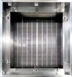
| Filter rack | A defined rack at the proposed location | Whether the location provides a physical mounting arrangement |
| Seal path | A defined seal path around the filter position | Whether the proposed arrangement includes a clear sealing interface |
| Inspection point | A defined point from which the installed stage can be inspected | Whether the location supports planned inspection access |
| Operating resistance | A means to observe resistance under a known airflow condition | Whether resistance observations at that location can be interpreted against a stated airflow condition |
A location that is correct from a protection-target and air-path standpoint still has to function as a physical installation point, and that functionality depends on conditions distinct from the ones already discussed. A proposed location needs a defined rack to hold the filter in position, a defined seal path so air does not bypass the filter media around its edges, a point from which the installed stage can be inspected, and a means of observing operating resistance under a known airflow condition.
These four conditions interact with each other in ways that are easy to overlook when a location is chosen primarily for its position in the air path. A location with ample duct space for a rack may not have equivalent access for an inspector to view that rack once it is installed behind other equipment. A seal path that performs acceptably at one airflow condition may behave differently if the system’s actual operating airflow differs from what was assumed when the rack and seal arrangement were specified. Where access is limited, inspection and service may require shutting down airflow or opening an adjacent section of the system, which changes how practical that location is to maintain over time compared with a location that allows a shorter, lower-disruption path to the filter.
Resistance monitoring deserves separate attention because an observed resistance reading is only meaningful relative to a known airflow condition. A reading taken without reference to the airflow at that moment cannot be compared reliably to a later reading taken under a different airflow condition, which undermines the value of tracking resistance over time at that location. If the proposed location does not include a means to establish or confirm the airflow condition at the time resistance is read, the readings from that location carry less interpretive value even if the physical sensing point itself is well placed.
Where a buyer is working from a facility’s or contractor’s drawings, supplying the intended placement conditions, rack dimensions, and planned access arrangement allows that information to enter a supplier’s configuration or quotation review in a way that matches the actual installation rather than a generic assumption about how the stage will be housed.
Verification boundaries for the completed filter train
| Reference | Relevant scope | Boundary for this placement decision |
|---|---|---|
| ISO 16890-1:2016 | Technical requirements and a particulate-matter-efficiency classification system for general-ventilation air filters | Does not prescribe the project stage layout or prove installed performance |
| ISO 14644-4:2022 | Cleanroom design, construction, start-up, and verification requirements | Does not prescribe a specific filtration technology or project layout |
| ISO 14644-3:2019 | Test methods for installed cleanrooms and clean zones | Does not establish a universal prefilter location or acceptance limit |
Once a prefilter location has been chosen and documented, it is reasonable to ask what a referenced standard can confirm about that choice, and the honest answer requires separating the scope of the referenced standard from the specific placement decision made on this project.
A standard such as ISO 16890-1:2016 addresses technical requirements and a classification system for general-ventilation air filters based on particulate-matter efficiency. This supports understanding how a given filter type is characterized and classified, but it does not prescribe where that filter should sit in a project’s stage layout, and it does not constitute proof of how the filter performs once installed in that specific air path.
Standards addressing cleanroom design, construction, start-up, and verification, such as ISO 14644-4:2022, establish a broader framework for how a controlled environment is built and brought into service. This framework does not specify a particular filtration technology or dictate a particular stage arrangement for a multistage HVAC system; the placement decision remains a project-specific exercise even where the surrounding facility falls under this kind of design and verification scope.
Test-method standards addressing installed cleanroom and clean-zone performance, such as ISO 14644-3:2019, describe how performance is measured once a system is in place. These methods confirm what the installed system achieves at the point of testing; they do not establish, in advance, a universal correct location for a prefilter stage or a fixed acceptance limit that applies independent of the project’s own design basis.
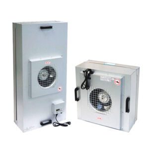
Taken together, these references support understanding filter classification, facility-level design and verification expectations, and installed-performance test methods, but none of them substitutes for documenting the specific air-path reasoning, interface conditions, and location-readiness checks that justify a prefilter’s position in a given system. Where a project team needs to defend a placement decision, that defense rests on the air-path tracing, interface documentation, and location checks performed for that project, with the referenced standards providing the surrounding classification and verification context rather than the placement answer itself. Reviewing a pre-air filter’s configuration options, including panel and bag-and-pocket arrangements, against this documented reasoning is what allows the physical equipment selection to match the placement logic already established for the project.
Frequently Asked Questions
Q: Should the pre-air filter go before or after the outdoor and return air mix?
A: Choose the stage only after tracing where both air streams enter and mix. Define the particulate load entering each candidate position and the coil, fan, downstream filter, or duct section that position is meant to protect.
Q: Can one pre-air filter location be assumed to protect every downstream component?
A: No single protection scope should be assumed from the filter name alone. Mark each intended protection target on the actual air path, then check whether the proposed stage is upstream of those targets and has a workable rack, seal path, and service point.
Q: How should two possible pre-air filter locations be compared?
A: Compare them under the same stated airflow condition and expected particulate load. For each location, record rack space, access for inspection and service, the sealing interface, and how operating resistance would be observed; an unresolved item is a design question to close before placement is assigned.
Q: What information should be prepared for a pre-air filter placement review?
A: Prepare an air-path sketch showing outdoor and return-air entry, the mixing section, coils, fans, downstream filters, and the proposed stage. Add the expected incoming particulate load, available rack space, access conditions, seal path, inspection point, and the airflow condition used for resistance observations.
Q: Do the cited ISO standards determine the correct pre-air filter location?
A: No. ISO 16890-1 provides general-ventilation filter requirements and classification scope, while ISO 14644-4 and ISO 14644-3 address cleanroom design, start-up, verification, and test-method scope; the project still needs its own stage layout and installed-performance verification.