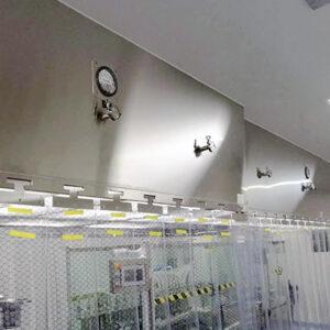
To commission HEPA terminal housings, you confirm the physical installation against the schedule, balance and record the airflow in its final state, run the installed leak test by the project’s specified method, restore the operating configuration, and file the results against each terminal tag. The sequence matters because each step changes the conditions under which the next one is valid: a damper adjustment on a shared branch moves flow at neighboring outlets, and a diffuser removed for scan access is not the assembly that delivers air in service. A terminal HEPA housing holds the final filter and its seal at the ceiling and relies on the upstream air handling system to supply air, so a commissioning result describes the installed assembly and its supply conditions together, not the filter element alone.
Walk Down the Installed Terminal by Tag
Before the ceiling closes or performance measurement begins, walk every tagged terminal against its schedule and drawing and confirm what is physically there. The checks are the installed filter identity, the seal seating at the housing-to-filter interface, the diffuser configuration, access to the damper, and whether the planned test connections can actually be made. Each of these decides whether a later number can be attributed to anything.
Filter identity is the item worth checking first because it is the one that cannot be inferred afterward. A terminal schedule assigns a size, efficiency grade and sometimes a specific filter to each tag; if the installed filter carries a different identifier, every airflow reading and every scan record filed under that tag describes a different assembly. Record the serial or identifier at the walkdown, while the filter face is accessible and the ceiling grid is open.
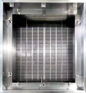
Seal seating and diffuser configuration decide whether the measurement represents the installed condition. A gel-seal or gasket-sealed housing depends on even compression of the filter against the knife edge or gasket face, and a partially seated filter can pass an airflow check while leaving a leakage path at the perimeter. Diffuser type changes the face velocity distribution and the discharge pattern, so a flow reading taken with a perforated face fitted is not interchangeable with one taken on a bare housing.
Damper access and test connections are practical constraints that are cheap to fix before the ceiling closes and expensive afterward. If the balancing damper sits above a hard ceiling with no access panel, the terminal cannot be rebalanced after a neighboring branch is adjusted. If the specified upstream challenge injection point or reference sampling point has no usable connection, the leak test cannot be run as written.
Some terminals are tested in a temporary configuration: a diffuser lifted for scan access, a flow hood adapter fitted, a test port opened in a duct. That is normal, and the walkdown is where you note it. Write down which configuration is temporary and list what must be re-verified once the terminal is returned to its service configuration, so the restoration is a tracked item rather than an assumption.
Balance the Airflow and Record the Final Settings
An airflow record is only reproducible if the conditions that produced it are recorded with the number. For each terminal, capture the scheduled flow, the measured flow, the room state and occupancy condition, the system mode the air handler was running in, the damper position, the diffuser configuration and the measurement method used. Then compare the measured value against the tolerance the project specifies for that terminal, since tolerance is a project parameter and not a property of the housing.
The reason for keeping conditions with the number is that a terminal flow is not a fixed attribute of the housing. It is the result of fan operating point, filter loading, system mode, the state of every other damper on the branch and the resistance of the diffuser fitted at the time. Strip those away and a later technician has a volume with no basis for comparison.
Shared branches make this concrete. When several terminals take air from one branch duct, closing a damper at one outlet raises the static pressure available to the others and increases their flow; opening one does the reverse. An individual reading taken early in the balance is a snapshot of a system state that no longer exists once the next damper is touched. Recheck the affected terminals at the final balance and keep those final readings paired with the damper settings that produced them.
Mark preliminary readings as preliminary when you take them. A proportional balance normally involves several passes, and the intermediate values are useful working data, but only the final-state readings belong in the acceptance record. Verifying the final state after balancing is what turns a working figure into a commissioning result.
Distinguish the measurement method as well. A flow hood reading at the diffuser face, a velocity traverse across the filter face and a duct traverse upstream do not measure the same thing under the same assumptions, and each carries its own correction and uncertainty. If two terminals of the same size were measured by different methods, the record should say so rather than present the figures as directly comparable.
Prepare for the Installed HEPA Leak Test
Readiness for an installed leak test is decided before the tester mobilizes: confirm the specified installed test method and its acceptance criterion, confirm that a usable upstream challenge and reference arrangement exists, and confirm that the filter face and the perimeter seal are accessible downstream across the planned scan coverage. A test crew that arrives to find no injection point or no reachable perimeter produces a schedule delay and a limitation entry, not a result.
The distinction that drives this is what the installed test is looking at. A factory or pre-installation element scan addresses leakage through the filter medium and its frame bond, and ISO 29463-4:2011 describes scanning high-efficiency filter elements for local leakage, with the public scope covering the element test rather than the installed housing interface. An installed test addresses a wider leakage boundary that includes the filter-to-housing seal, the housing itself and the housing-to-ceiling interface. IEST-RP-CC034 is written to cover HEPA and ULPA leak-test scope at the factory, before installation and after installation, with the detailed procedures and criteria outside the public summary, so the applicable method and criterion come from the project’s approved protocol.
Method selection also carries conditions. ISO 14644-3:2019 sets out test methods and apparatus for cleanroom performance testing under different airflow types and occupancy states, and the method has to suit the cleanroom or clean zone in question; the standard does not supply a universal acceptance limit for a terminal. The upstream challenge concentration, the aerosol used, the photometer or particle counter arrangement and the scan rate and probe standoff therefore come from the specified method, not from general practice.
The practical readiness questions are physical. Can an aerosol be introduced far enough upstream to be uniform across the filter face, and can a representative upstream reference sample be drawn? Is there enough clear space below the terminal, including at the perimeter where the gel seal or gasket meets the housing, for the probe to travel across the whole planned coverage? Obstructions such as light fittings, sprinkler heads, process equipment or a fixed diffuser frame commonly block part of the perimeter.
Where required coverage cannot be reached, the limitation is logged as a limitation. What happens next — a partial-coverage disposition, a modification to gain access, or a different test arrangement — is set by the project-authorized disposition and its designated approver, not by the test crew on the day.
Restore the Operating Setup and Close Test Failures
Airflow measurement and leak scanning often need different physical configurations at the same terminal, so record each configuration separately and then restore the specified operating configuration before the terminal is considered finished. A perforated diffuser face lifted for scan access, a damper opened fully to raise challenge velocity, or a flow-hood adapter fitted for a hood reading all describe assembly states that are not the service state.
Where the configuration change can alter the result, re-verify the affected item. If the damper was moved for the scan, recheck the terminal flow in the restored position. If the diffuser was removed for the scan and the specified coverage includes the face as installed, confirm what the coverage check means with the diffuser refitted. Consider a terminal tagged T-A where the diffuser is lifted for the scan and the branch damper is opened to meet the challenge velocity: both changes are logged, the damper is returned to its balanced position, the diffuser is refitted, and the airflow is re-read in that final state before the terminal is signed off.
Failures need the same discipline. When a scan shows a leak or an airflow reading falls outside the project tolerance, record the terminal tag, which check failed, and the exact location on the filter face or seal perimeter, or the operating condition under which the flow was out of tolerance. “Terminal T-A failed” is not actionable; “leak at the downstream perimeter, left-hand corner adjacent to the clamp” tells the next person what to fix.
Keep air delivery and integrity as separate acceptance decisions, because they fail for different reasons and are corrected by different work. An out-of-tolerance flow usually points to damper position, branch balance, fan operating point or filter loading. A leak points to seal compression, housing damage, filter medium damage or an installation fault at the ceiling interface. Treating them as one combined pass/fail obscures which corrective action was actually taken.
Every corrective action should be logged and the retest linked back to the original failure, so the record shows that the specific defect was addressed rather than that a second test happened to pass. Where the approved protocol requires retesting beyond the item that failed — for example, rescanning a filter after reseating it, or rebalancing a whole branch after a damper change — follow the broader scope the protocol sets. Closure of a deviation and release of the terminal are decisions for the project’s approved procedure and its designated approver.
Build the Handover Record by Terminal
| Record | Fields to keep with the tag | What it lets you verify |
|---|---|---|
| Final airflow balance | Scheduled and measured flow, system mode, room state, damper position, diffuser setup and method | The terminal met its flow criterion in the recorded final state |
| Installed integrity test | Filter identifier, scan setup and coverage, method and criterion, instrument and calibration reference, result | The leak result belongs to that installed filter and test configuration |
| Deviation and retest | Affected check and location or state, corrective action, linked retest and disposition | The recorded correction addresses the original failure |
The handover record is organized by terminal tag, and everything that describes that terminal’s commissioning sits under its tag: the filter serial or identifier, the approved method and criterion applied, the instrument used with its calibration reference, the final test conditions and results, any deviations, the linked retests and the disposition. One tag can carry several distinct records — a final airflow balance and an installed scan on the same filter — and keeping them linked but separate preserves the fact that they are different acceptance decisions.
The test is whether a technician returning in two years can identify what was tested and compare a new result on the same basis. That requires the conditions as much as the results: the system mode and room state behind a flow figure, the scan setup and coverage behind a leak result, and the instrument identity behind both. A photometer reading with no calibration reference and no record of which upstream concentration it was referenced against cannot be meaningfully compared with a later reading.
Deviation records belong with the terminal rather than in a separate exception log. Keeping the failure, the corrective action, the linked retest and the disposition together means the history reads in sequence and nobody has to reconstruct which retest answered which failure. It also makes clear which terminals were corrected during commissioning, which is useful information when a filter is later changed or a room is requalified.
Finally, keep these commissioning records distinct from the ongoing monitoring data the facility will generate afterward. Commissioning records describe the installed condition at acceptance under defined test conditions; routine monitoring describes the room in operation over time. They answer different questions and are judged against different criteria, and blending them makes both harder to interpret.
Before a commissioning or testing supplier can scope this work, have the terminal schedule with tags and scheduled flows, the ceiling and duct drawings showing damper and access-panel locations, the airflow and pressure scheme with the intended room states and system modes, the project’s specified installed test method and its tolerance for each terminal, and the filter identifiers as actually installed.
Frequently Asked Questions
Q: Can I file a passing scan report that lists filter serial numbers but no terminal tags?
A: Only file it as terminal evidence after the serial numbers are reliably mapped to the installed tags. Attach that mapping to the record; keep any unmatched result open rather than assigning it by room or date alone.
Q: What should I record if airflow passes but the installed scan is postponed?
A: Record the airflow result with its final setup and leave the integrity item open. Note why the scan was postponed and what has to be in place for the follow-up; any release decision follows the project protocol.
Q: Can an earlier terminal reading still be used if another outlet was rebalanced?
A: Keep it as the earlier reading. Where the outlets share a branch, remeasure the affected terminals at the final settings and link the new values to the earlier record so the handover identifies which state applies.
Q: What if only the diffuser was removed for the test and the filter stayed seated?
A: Record the removed face as the test configuration and note the restored face in the operating record. Decide whether the airflow result needs rechecking by whether it was measured with that final face and whether any setting changed.