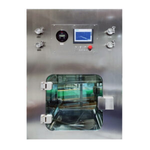
Verifying HEPA integrity after high-temperature cycling means comparing the same evidence set — filter records, visual condition, airflow behavior, resistance across the filter, and installed leakage evidence — before and after an agreed thermal sequence, and tracking the element, the frame-to-seal joint, and the seal-to-housing interface as three separate items. The comparison only means something if the test state, access arrangement, test method, and acceptance criteria are fixed in the project protocol before the baseline is taken, because changing any of those between the two readings changes the result independently of the filter. High-temperature HEPA thermal cycling stresses media, sealant, gaskets, and housing differently, so a changed reading is a signal to localize, not a verdict on the assembly as a whole.
Thermal sequence and verification checkpoints
| Checkpoint | Evidence to compare | Decision supported |
|---|---|---|
| Baseline before the agreed thermal sequence | Filter records, visual condition, airflow behavior, resistance, and leakage evidence | Establishes the reference set for later comparisons |
| Post-cycle checkpoint defined in the project protocol | The same evidence set, taken under the protocol-defined test state | Shows whether the result remains consistent with the baseline under the agreed duty |
| Investigation after an out-of-family result | Checkpoint result plus recent cycle, installation, housing, airflow, and measurement records | Supports localization and evidence review before repair or replacement is selected |
A verification plan starts by writing down the thermal sequence itself: the temperature range the filter will see, how the ramp is run, how long it holds, and how many cycles occur between checkpoints. Without that definition, a post-cycle reading has no duty history attached to it and cannot be compared meaningfully with anything.
Checkpoints then anchor the comparison. A baseline is taken before the agreed sequence begins; a post-cycle checkpoint is taken after the duty defined in the protocol; and an investigation checkpoint is triggered when a result falls out of family with the earlier ones. The value of this structure is that each checkpoint collects the same five classes of evidence, so a later difference can be attributed to a specific change rather than to a different way of measuring.
The five classes are worth keeping distinct because they fail differently. Filter records carry identity and factory history. Visual condition catches media damage, sealant distortion, or gasket set that an instrument may not resolve. Airflow behavior and resistance across the filter reflect loading and flow conditions, and can move for reasons that have nothing to do with leakage. Installed leakage evidence addresses the one question the others cannot: whether particles are bypassing the media or the seals in place. Treating resistance drift as evidence of a leak, or a clean scan as evidence of stable resistance, is a common specification mistake that leaves gaps in the record.
Thermal cycling matters here because expansion and contraction act on dissimilar materials at different rates. Media, potting compound, frame, gasket, and housing move relative to one another on every cycle, and the cumulative effect appears at joints before it appears in the media. That is why the checkpoint plan should be written around the sequence rather than the calendar.
Baseline evidence for the filter element
The factory scan result is the element baseline. A scanned high-temperature HEPA filter arrives with documented evidence of where, if anywhere, local leakage was detected across its face under the test conditions used at the factory, and that record is the reference against which later element-level findings are read.
ISO 29463-4:2011 describes a scan method for determining leakage of high-efficiency filter elements, and the scope of that test is the element. It tells you how the media and its potting behaved as a discrete article under test conditions; the state of the installed assembly — the filter sitting in its frame, compressed against a gasket, inside a housing in a duct or ceiling grid — is established by installed testing after the filter is mounted. Both pieces of evidence are needed, and keeping them separate is what makes a later finding interpretable.
For high-temperature service, the baseline record should also capture what the element is built from, since the thermal rating is a property of the element and its sealing materials. High-temperature HEPA air filters are constructed with media, separators, frame, and sealant selected for sustained elevated temperature; the rated continuous and peak temperatures and the sealing material belong in the filter record alongside the scan result. If the planned thermal sequence approaches or exceeds what the element is rated for, that is a specification question for the filter datasheet before any verification plan is written, not something a post-cycle test can resolve.
Record the baseline visual condition at the same time, with enough detail to be comparable: media and separator condition, sealant surface, gasket face, and any handling marks present on arrival. A photograph set taken before installation costs little and settles arguments later about whether damage predates the thermal duty.
Interface checks at the frame seal and housing
| Path to track | Evidence to compare | Interpretation boundary |
|---|---|---|
| Filter element | Factory scan baseline and element leakage evidence | Element scan evidence does not establish installed housing integrity |
| Frame-to-seal joint | Visual condition and installed leakage evidence at the joint | A change at this interface should be separated from the element result |
| Seal-to-housing interface | Housing condition and installed leakage evidence at the housing interface | A change on the housing side should not be attributed to the element without supporting evidence |
Three leakage paths exist in an installed HEPA assembly, and each is verified by different evidence: the element itself, the joint between the filter frame and its seal, and the interface between that seal and the housing. Keeping them separate is the difference between a finding that points to an action and a finding that condemns the whole assembly.
The physical distinction is straightforward. A leak through the element is a defect in the media or in the bond between media and frame, and it travels with the filter. A leak at the frame-to-seal joint is a problem of contact between the filter’s sealing surface and the gasket or fluid seal — uneven compression, a set or hardened gasket, a distorted frame flange. A leak at the seal-to-housing interface sits on the housing side: a warped or corroded knife edge, a damaged gel channel, loose or unevenly tightened clamping hardware, or a housing that has moved relative to its duct connection. Thermal cycling acts on all three, but it acts hardest where dissimilar materials are clamped together and must return to the same position after each cycle.
Localization requires access. If the installed test cannot distinguish a leak at the gasket perimeter from a leak in the first inch of media, the record will attribute both to the element, and a replacement filter will be installed against a housing fault that remains. Plan the scan coverage so the perimeter, the frame joint, and the housing interface can each be traversed, and note in the record which paths the access actually allowed.
Clamping behavior deserves specific attention after thermal duty. Gaskets take a compression set, fasteners can relax, and fluid seals can be displaced if the filter has been disturbed. A visual and mechanical condition check of the clamping arrangement, recorded with the leakage result, often explains an out-of-family reading that the element evidence alone would leave unaccounted for.
Installed leak-test method state and access
| Protocol field | What the project must specify | Why it affects the decision |
|---|---|---|
| Installed leak-test method | The agreed method for collecting installed leakage evidence | Factory element scanning alone does not verify installed housing integrity |
| Test state | The operating or test state used at each comparison checkpoint | Baseline and post-cycle results need an agreed state for interpretation |
| Access | The access arrangement used for the installed test | Access must support the leakage-path checks included in the protocol |
| Acceptance criteria | The project-specific criteria applied to the installed result | ISO 14644-3 does not supply a universal thermal-cycle acceptance limit |
The installed test is defined in the project protocol, and four fields have to be filled in before the baseline is taken: the installed leak-test method, the test state, the access arrangement, and the acceptance criteria. Fix them once and apply them identically at every checkpoint, because a comparison between two differently conducted tests is not a comparison.
IEST-RP-CC034.5 sets out the scope for factory, pre-installation, and installed filter leak tests, and that three-way distinction is the reason the field matters: the method appropriate to a filter on a test rig is not the method that verifies an assembly in place. The published scope summary identifies what each category of test covers; the procedure and acceptance detail sit in the paid text, so the project protocol should cite the specific practice it is following rather than a general reference to leak testing.
Test state covers the operating conditions under which the reading is taken — airflow condition, the thermal state of the installation at the time of test, upstream challenge arrangement, and whether adjacent equipment is running. For high-temperature installations, the thermal state is not a detail. Seals and frames sit in different positions hot and cold, and a baseline taken cold compared against a post-cycle reading taken warm will differ for reasons that have nothing to do with integrity. Decide which state the protocol uses and hold it.
Access determines what the test can see. Upstream challenge injection and downstream scanning both need physical reach, and in ducted or ceiling-mounted installations that reach has to be designed in rather than improvised. Test ports, scan clearance in front of the filter face and around its perimeter, and a safe working position at elevated-temperature equipment are specification items for the housing, and they are far cheaper to add during design than to retrofit around a filter that cannot be tested where it sits.
Acceptance criteria are project-specific. ISO 14644-3:2019 provides test methods for installed cleanroom and clean-zone performance, and it does not supply a universal acceptance limit or a thermal-cycle protocol. The criteria applied to your installed result come from the project’s approved procedure, informed by the room classification, the process, and the filter’s rated performance, and the person designated in that procedure decides whether a result is accepted.
Investigation path for a changed result
| Evidence category | Review focus | Question for the decision record |
|---|---|---|
| Recent thermal cycles | Sequence and checkpoint history since the baseline | Does the change align with the recorded cycle history? |
| Installation work | Work performed since the last accepted result | Did an installation intervention precede the changed result? |
| Housing condition | Recorded visual condition and housing-side leakage evidence | Is there evidence that the housing or its interface needs attention? |
| Airflow behavior | Airflow changes and resistance compared with the baseline | Were the comparison conditions materially different? |
| Measurement conditions | Test method, state, access, and criteria used for both results | Are the results comparable under the agreed protocol? |
An out-of-family result is an instruction to review the record, not a trigger to replace the filter. The review covers five categories before any attribution is made: the thermal cycle history since the baseline, installation and maintenance work performed in the interval, housing condition, airflow behavior and resistance, and the measurement conditions used for both readings.
Start with measurement conditions, because that review is quick and frequently decisive. If the test state, access, method, or operator differed between the two readings, the results may not be comparable at all, and the fastest correct action is to repeat the test under the protocol conditions. Only when the two readings are genuinely like-for-like does the result carry information about the installation.
Cycle history tells you whether the duty actually imposed matches the duty the verification plan assumed. An excursion beyond the element’s rated temperature, a faster ramp than planned, or a cycle count well above the interval between checkpoints all change what the reading means, and all belong in the record before conclusions are drawn.
Installation work is the next thing to look at. A filter change, housing maintenance, duct work, or even access by another trade in the interval can disturb clamping or displace a seal. If an intervention preceded the changed result, the frame-to-seal and seal-to-housing paths deserve attention before the element does.
Housing condition and airflow evidence then complete the picture. A corroded or deformed sealing surface points to the housing side. A resistance change without a leakage change points toward loading or a flow change rather than integrity. The output of this review is a localized finding — one of the three paths, with the evidence that supports it — which is what the repair or replacement decision is made against. Whether the system returns to service, and on what evidence, is determined by the project’s approved procedure and its designated approver.
Repair retest or replacement decision record
| Decision stage | Evidence to retain | Record boundary |
|---|---|---|
| Localized finding | The affected element, frame-to-seal joint, or seal-to-housing interface and the supporting evidence | Keep the finding tied to the identified path rather than the HEPA assembly as a whole |
| Repair and retest | Repair scope plus the retest method, test state, access, acceptance criteria, and result | The repair decision is complete only when the follow-up result is recorded against the agreed protocol |
| Replacement | Investigation evidence supporting replacement, replacement filter records, and factory scan baseline | The replacement element baseline does not by itself establish installed housing integrity |
| Final disposition | Post-action visual, airflow, resistance, and leakage evidence | State whether the result meets the project-specific criteria; do not imply a universal thermal-cycle limit |
The decision record ties the chosen action to the localized finding and to the verification that follows it, so that anyone reading the file later can see which path was implicated, what was done, and what evidence closed the matter. A record that says “filter failed, filter replaced” is not traceable; one that identifies the seal-to-housing interface, the housing repair performed, and the retest result against the stated criteria is.
Four entries carry the record. The localized finding names the affected path — element, frame-to-seal joint, or seal-to-housing interface — with the evidence supporting that attribution. A repair entry states the repair scope and then the retest conducted under the same method, state, access, and criteria as the original test; the repair is not documented until that follow-up result is in the file. A replacement entry carries the investigation evidence that led to replacement, the new filter’s records, and its factory scan baseline, with the understanding that the new element’s scan establishes element condition and the installed test establishes how the new assembly behaves in place. Final disposition records the post-action visual, airflow, resistance, and leakage evidence, and states the result against the project-specific criteria rather than against any implied general limit.
One practical point about replacement: if the investigation implicated the housing, replacing the element will produce a filter with a clean factory baseline sitting against the same defective interface, and the next installed test will reproduce the finding. Decide the housing question first.
Where the same path keeps reappearing across cycles — the same gasket face, the same housing corner — the useful conclusion is usually about material selection or clamping design for the thermal duty, not about the individual filter. That is a design conversation, and it goes better when you bring the thermal sequence as actually run, the filter records including the element’s rated temperature and sealing material, the installed test protocol with its method, state, access and criteria, the housing drawings showing the sealing arrangement and test access, and the checkpoint history that shows how the readings moved.
Frequently Asked Questions
Q: Can the factory scan be used as proof that the complete installed HEPA assembly remained intact after thermal cycling?
A: No. Use the factory scan as the filter element baseline, then verify the installed condition under the project protocol so the element, frame-to-seal joint, and seal-to-housing interface can be assessed separately.
Q: When are baseline and post-cycle integrity results suitable for direct comparison?
A: They are suitable when the agreed test method, test state, access arrangement, acceptance criteria, and evidence set are consistent at both checkpoints. If a material condition changed, resolve that comparability issue before treating the difference as evidence of damage.
Q: Does a change in airflow behavior or resistance prove that the HEPA filter is leaking?
A: No. Treat it as an investigation trigger and compare it with visual condition and leakage evidence while checking the element and both installed interfaces separately. This prevents an operating change from being assigned to the filter element without supporting evidence.
Q: When should an out-of-family result be treated as inconclusive rather than as a failed filter?
A: Treat it as inconclusive when the baseline and post-cycle measurements cannot be shown to share the agreed method, state, access, and criteria. Re-establish comparable measurement conditions and document the repeat result before attributing the change to a leakage path.
Q: What should determine whether the next step is repair, retest, or replacement?
A: Base the decision on a localized finding supported by the cycle history, installation-work record, housing condition, airflow and resistance comparison, and measurement conditions. Record the selected action and verify its outcome against the same project-specific protocol; a replacement element’s factory baseline still does not establish installed housing integrity.