Whether an FFU system draws from a shared ceiling plenum or receives air through individual duct connections is one of the earliest boundaries a cleanroom project must draw—and leaving it open forces every downstream decision about ceiling structure, controls, and commissioning responsibility to stay open with it. The choice is not universal: plenum feed suits layouts where the building AHU system already conditions the interstitial space to the required state; ducted supply suits layouts where each FFU needs an explicit, traceable inlet condition and the ceiling void is not configured as a pressure vessel. Neither path is inherently cleaner or more reliable; what differs is which party owns which interface.
Map the two proposed air paths
Every FFU system begins at the same point—conditioned air enters the unit, passes through the HEPA filter, and discharges downward into the work zone—but the upstream boundary is completely different depending on how that air arrives.
In a plenum-fed arrangement, the interstitial ceiling void is pressurized with conditioned supply air, typically by a central air handling unit serving the room below. The FFU draws from this shared volume passively: its fan pulls air through the plenum opening, through the HEPA filter, and into the cleanroom. The plenum acts as a low-velocity buffer, smoothing pressure variation across all units drawing from the same volume. This arrangement is a natural fit when the building structure already incorporates a finished interstitial space and when the AHU package is scoped to maintain the plenum at the temperature, humidity, and cleanliness state the process requires.
FFU air-source interface decision checks
| Project condition | Buyer action | Boundary to retain |
|---|---|---|
| The supply route is undecided | Show shared-plenum and duct-feed sections | Neither is universally preferable |
| A shared plenum is proposed | Identify who defines and supplies its conditioned air | No temperature or humidity performance is inferred |
| Duct feed is proposed | Show connection geometry and quoted inlet conditions | No universal duct pressure is given |
In a ducted-feed arrangement, each FFU (or a group of units on a common branch) receives conditioned air through a dedicated duct connection terminating at the unit inlet. The duct system defines a physical boundary: the air at that connection point has a quoted pressure, temperature, and flow rate, and those values are the FFU’s operating input. The fan still draws through the HEPA and delivers filtered air downward, but the upstream hydraulic path is explicit and isolated from neighboring units. This path is more common when the ceiling void is unfinished, when independent isolation of zones is required, or when the project demands a documented supply condition for each unit.
The air path is not just a routing question—it is a question of who owns the pressure, the temperature, and the cleanliness of the air before it enters the FFU.
Both paths can deliver equivalent clean air at the work surface. What they cannot share is the same interface responsibility.
Compare plenum and duct responsibilities
The practical difference between the two arrangements shows up most clearly when the project team maps who supplies what and where one contractor’s scope ends and another’s begins.
In a plenum-fed system, the FFU package typically covers the units themselves, their filters, their speed controls, and their mechanical attachment to the ceiling grid. What the FFU package does not cover—and must not be assumed to cover—is the conditioning of the plenum air. Temperature, humidity, and cleanliness inside the plenum are governed by the AHU system, which is usually a separate scope under a separate contractor or the building mechanical package. If that upstream system is undersized, inadequately filtered before the plenum, or unable to maintain plenum pressure under varying load, no adjustment to the FFU will correct it. Any performance claim tied to the FFU alone—room temperature stability, humidity control, ISO classification downstream of the HEPA—depends on the upstream system delivering air that meets the assumed inlet condition.
Related Products
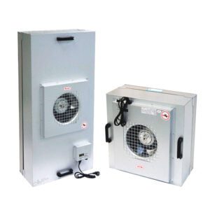
- Fan Filter Unit – FFU — Review the unit family against the documented airflow and interface brief.
- Mini Pleat HEPA/ULPA Air Filter — Check the filter family when defining the unit and replacement-filter boundary.
- Gel Seal HEPA/ULPA Air Filter — Review this filter interface option only where the proposed unit uses a compatible mating arrangement.
- Wall & Ceiling System — Coordinate the ceiling and plenum building interface with the proposed FFU arrangement; confirm the exact project scope.
Ducted supply shifts this boundary explicitly onto the duct system. The duct connection carries a quoted inlet pressure, usually low-positive and project-defined, and the FFU is specified against that quoted value. If the duct system cannot sustain that pressure under all operating states (full occupancy, partial load, one zone isolated), the FFU operates outside its design point. That deviation belongs to the duct design, not the FFU.
Consider a project where a pharmaceutical client assigns the AHU, ductwork, and FFU package to a single mechanical contractor. In that case the boundary disappears internally, but it is still worth writing down: when something goes wrong during commissioning, the team needs to know whether the fault is upstream or downstream of the HEPA. Without a named boundary, the diagnostic conversation has nowhere to start.
A practical tool for any project where supplier scopes differ is a short responsibility matrix—four columns, one row per interface: the item (plenum volume, duct connection, unit inlet, speed controller, filter, monitoring point), who designs it, who supplies it, and who commissions it. A missing row in that table is the gap most likely to surface during installation.
The key items to assign:
- Plenum enclosure or duct system (design, structure, airtightness)
- Conditioned air supply to the plenum or duct inlet (AHU, coils, pre-filtration)
- FFU units, HEPA filters, and fan assemblies
- Speed controls, variable frequency drives, or EC motor interfaces
- Room pressure monitoring and feedback signals
- Ceiling grid and FFU mounting hardware
No single arrangement is universally turnkey. Even a single-supplier project should document these lines because commissioning and maintenance personnel change.
Coordinate controls and service space
Controls coordination is where the two air-path architectures diverge most sharply in day-to-day operation.
In a plenum-fed system, slowing down an individual FFU reduces its draw from the plenum but does not reduce the AHU output. If a large number of units are slowed simultaneously, plenum pressure may rise, which changes the inlet condition for every other unit in the same plenum zone. The fan in each FFU will respond to that changed inlet differently depending on its control mode. No single FFU setting describes the whole air path; the system response under partial-load or zone-isolated conditions needs a coordinated operating-state description from both the AHU designer and the FFU control engineer. Projects increasingly ask for that description in the form of a written sequence of operations that covers normal run, reduced load, single-zone isolation, and emergency exhaust modes.
Ducted systems are easier to analyze zone by zone but require the duct designer to account for changing FFU demand. If variable-speed FFUs on a common duct branch ramp down together, duct static pressure can climb unless the upstream fan is modulated to match. That modulation logic belongs to the duct controls, not the FFU controls—another interface that must be assigned and documented.
Ceiling access ties directly to both architectures. In a plenum-fed system, the plenum above the FFU is a pressurized, occupied air volume. Any access for filter change or fan service draws from that volume and must be planned so that the ceiling opening does not short-circuit clean air back into the work zone or admit unfiltered air from adjacent spaces. The removal route for a FFU or a filter bank—size, swing clearance, temporary support—must be overlaid on the ceiling plan before the grid is finalized. No universal clearance value applies; it follows the unit dimensions, the filter size, and whether the unit slides horizontally, drops vertically, or requires the grid panel to come out first.
In a ducted system, the duct connection at the top of the unit adds a mechanical disconnection step to filter or fan service. That connection—flanged, slip-fit, or flexible—must be reachable from above or from the room side, and the method of sealing it during service must be agreed before installation. Projects that design the ceiling access route after the ductwork is fixed regularly discover that the duct connection lands exactly where the service technician needs to stand.
Freeze the service access route at the same time as the air-source boundary; changing either one after ceiling installation usually changes both.
Related Reading
- Map the Protected Process First: A Zone-by-Zone Brief for FFU, LAF, and HEPA Selection — Define the upstream process-zone brief before narrowing equipment scope.
- FFU, LAF, and HEPA Housing Interfaces: What to Confirm for Ducts, Power, Controls, and Service Access — Coordinate the neighboring air-path and utility responsibilities.
- FFU Maintenance Planning for Modular Cleanrooms: Access, Replacement and Testing — Plan the downstream service and evidence boundary before the unit layout is fixed.
Freeze the air-source brief
The air-source boundary is the single document that closes the gap between mechanical design and FFU specification.
Before an FFU system can be specified with confidence, six items need a named value or a named owner:
- Air-source type: plenum or ducted, and the physical extent of each zone
- Inlet condition: temperature range, humidity range, and cleanliness class of air at the FFU inlet, supplied by the AHU designer
- Inlet pressure: static pressure at the plenum face or duct connection, quoted by the mechanical engineer for each operating state
- Controls interface: what signal the FFU receives (BAS analog, digital network, local switch), who provides the controller, and what feedback the FFU sends upstream
- Ceiling interface: grid type, FFU mounting method, filter access side, and the removal path for each unit type
- Scope boundary: the named contract or package that owns each item above
YOUTH configures FFU systems against a defined air-source brief, which means the specification conversation starts with these six items rather than with unit selection. Where one or more items are still open, the brief should record who is responsible for closing them and by which project milestone—not because the FFU package can substitute for that decision, but because an open item here is a held specification everywhere downstream.
If the upstream air system is still being scoped when the FFU package is being specified, the minimum useful step is to agree on the inlet pressure range and temperature envelope, even as estimates. Those two values set the fan duty and filter sizing, and changing them after units are ordered is the scenario that most commonly forces a re-scope. Fixing the air-source boundary early is not about locking the design prematurely; it is about ensuring that every party specifying equipment in the ceiling zone is working from the same upstream assumption.
References
- ISO 14644-4:2022 Cleanrooms and Associated Controlled Environments – Part 4: Design Construction and Start-Up — Use the public requirements-to-verification scope to organize the project brief; it does not select a technology or contract model.
- ISO 14644-3:2019 Cleanrooms and Associated Controlled Environments – Part 3: Test Methods — Locate the installed performance-test scope; its summary provides no universal project acceptance limit.
- IEST-RP-CC036 Testing Fan Filter Units — Compare FFU test subjects before requesting matched operating-point evidence; detailed methods remain outside the public summary.
- ISO 14644-7:2004 Cleanrooms and Associated Controlled Environments – Part 7: Separative Devices — Distinguish local-device design scope from whole-process protection.
Frequently Asked Questions
Q: What if a duct-fed proposal arrives after a plenum-based layout was accepted?
A: Treat it as an interface change rather than a like-for-like substitution. Review the new connection route, inlet assumptions and control responsibilities against the existing ceiling and service arrangement before accepting the revised unit scope.
Q: Who should decide when the FFU and upstream air system have separate controls?
A: Resolve the intended operating states jointly across the two packages. If one package changes supply while the other changes unit settings, the project needs an agreed account of their interaction rather than two independent component descriptions.
Q: Can a supplier quote both routes while the building design remains open?
A: Yes, as explicitly separate options. Give each option its own air-source assumptions, connections and responsibility boundary so that an attractive unit price does not hide a different upstream package.